DMC HC134 Скачать руководство пользователя страница 9

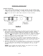
PREVENTATIVE  MAINTENANCE 

It  is  recommended  that  the  following  maintenance  be  performed  at  30  day  intervals 

on  all  HC1 34  tools  which  are  in  REGULAR  DAILY  SERVICE. 

CLEANING  AND  LU BRICATING  THE  TOOL  HEAD: 

Inhi bitor  with  grit  is  a  highly  abrasive  compound  which  must  be  cleaned  from  the 

tool  head  at  freq uent  intervals.  The  procedure  shown  in  LUBRICATING  THE  TOOL  HEAD 

should  be  followed  to  prevent  excessive  wear  on  the  internal  parts  of  the  tool  head. 

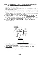
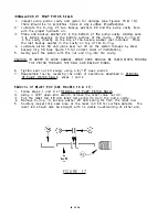
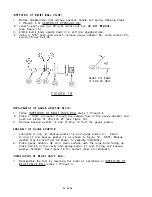
CHEC K  THE  SYSTEM  PRESSURE: 

1.  Check  relief  valve  pressure  setting  using  a  DMC  HPG-1  Pressure  Gauge  (see 

ADJU STING  PUMP  SYSTEM  PRESSU RE). 

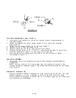
CHEC KING  PUM P  OIL  LEVEL: 

1.  Check  reservoir  oil  level  of  tool  by  rotating  the  advance  handle  clockwise.  Oil 

supply  is  adequate  if  the  indenters  touch  before  the  Qdvance  hQndle  is  c o mpletely 

advanced.  Ad d  oil  if  req uired  (see  ADDITION  OF  HYDRAULIC  OIL). 

LOSS  OF  HYDRAU UC  OIL: 

Hydraulically  actuated  tools  will  gradually  lose  their  hydraulic  oil  over  a  period  of 

time.  This  loss  is  caused  by  the  a dherence  of  small  amounts  of  oil  to  the  moving 

parts  exposed  to  the  outside,  such  as  the  plungers,  pistons,  and  rams,  and  from 

occasional  leakag e  around  mechanical  seals.  A  small  loss  of  hydraulic  oil  is  normal 

and  will  not  affect  the  operation  of  the  HC134  tool.  However,  if  the  level  drops  too 

low  air  can  become  trapped  in  the  hydraulic  system  causing  the  tool  to  develop  a 

"spongy"  feel,  preventing  it  from  operating .   Occasional  hydraulic  oil  checks  can  be 

performed  as  follows. 

P REVENTATIVE  MAINTENANCE  PROCEDURES 

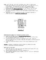
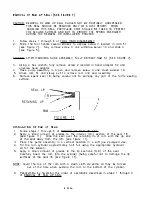
LU BRICATING  TH E  TOOL  H EAO : 

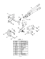
1.  Disassem ble  the  tool  head  (see  TOOL  HEAD  DISASSEMBLY  steps  1  through  6)  and 

clean  parts  thoroughly  by  washing  in  an  environmentally  approved  solvent.  Wipe 

parts  clean  and  apply  a  coating  of  grease  (see  LUBRICATION  RECOMMENDATIONS) 

to  the  beari n g   Qnd  pin  surfaces  of  Slide  4  {see  Figure  5)  and  the  beari n g   surfaces 

of  each  indenter  (see  Figu re  6). 

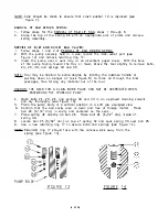
2.  Place  bearing  case  11  on  the  bearing  surfaces  of  the  indenter  and  apply  a  small 

amount  of  grease  in  each  roller  cavity  of  the  bearing  case.  Place  bearing  1 6   in 

each  slot  of  case  1 1   a nd  pack  a  small  amount  of  grease  after  all  the  rolle r  are 

installed. 

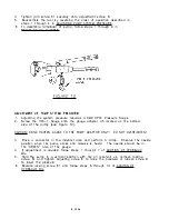
3.  Follow  steps  1  through  2  of 

TOOL  HEAD  ASSEMBLY. 

4.  Wipe  lubricant  from  indenter  cri mping  surfaces. 

6  OF  2B 

Содержание HC134

Страница 1: ...0 Cl 00 0 0 HC134 4 INDENT DIE LESS CRIMP TOOL DI DANIELS MANUFACTURING CORP IIIIIIIIP ORLANDO FLORIDA d DwM CAGE 11851 DATE 12 01 REVISION C COPYRIGHTC 2001 ALL RIGHTS RESERVED DANIELS MANUFACTURING...

Страница 2: ...ed F O B factory Orlando Florida d DMC disclaims any liability whether under this warranty or otherwise for any failure of its products which is caused in whole or in part by the use in or with that p...

Страница 3: ...er 0 Ring 10 Inspection Replacement of Pressure Adjusting Valve 11 Installation of PSI Valve 11 Adjustment of Pump System Pressure 12 Removal of Ram Lip Seal 13 Installation of Ram Lip Seal 13 Removal...

Страница 4: ...DVANCE MANUAL RETRACT ADVANCE HANDLE 0 BRIDGE LOCKING PIN 4 INDENTERS 1 FIXED 3 MOVABLE RELEASE ROD HANDLE RELEASE PIN ROTATE AND DEPRESS HANDLE TO RETRACT INDENTERS PUMPING STROKE OR RETRACT PUMP HAN...

Страница 5: ...GENERAL MAINTENANCE The HC134 is a hydraulic crimp tool which requires well trained experienced personnel having a clean work area equipped with adequate tools for major repairs adjustments or mainten...

Страница 6: ...chanism if not regularly removed Wipe entire tool thoroughly with a clean dry or slightly oily cloth after daily use 2 DO NOT MAKE ADJUSTMENTS TO THE TOOL There are no adjustments on this tool that ca...

Страница 7: ...ne marked on the barrel see Figu re 2 Rotate each successive cri m p 45 NOTE The n um ber of crimps wil l vary with each size sleeve or termina l 3 Insert the cond uctor into the con nector socket ma...

Страница 8: ...nced per the instructions a bove before crim ping sma ll sleeves RIGHT FIG URE 4 REMOVING A S PLIC ED CABLE 6 Rotate bridge locking pin clockwise and pu II pin to ope n u pper bridge see Flg ure 1 and...

Страница 9: ...to the moving parts exposed to the outside such as the plungers pistons and rams and from occasional leakag e around mechanical seals A small loss of hydraulic oil is normal and will not affect the o...

Страница 10: ...34 3 2 HC1J4 2 1 HC1 34 1 1 reM PART NO l 3 1 V 5 1 HYDRAULIC PUMP 1 115 32 X 1 1 25 LC SPRINC PIN 2 1 4 ZO X 1 Lil 501ll ET CN 5CR 2 E RING 51 33 31 2 10 32 X 1 LG SIClCKET CAP 9CR 1 2 ROLLER BEARING...

Страница 11: ...ut a nd get lost 7 Check spring pin 25 ma king sure the ends of th e pin a re fl ush o r below the su rface of swivel 1 4 TOOL HEAD ASSEMBLY 1 Reassemble the tool by reversin g the step by step sequen...

Страница 12: ...P BODY 30 8 1 1 B5 PLUNGER SPRING 29 8 1 1 84 RAM RElURN SPRIN G 1 9 4 1 453 COPPER CRUSH WASHER 1 8 4 1 452 VARISEAL 1 6 4 1 422 0 RI NG 1 3 4 1487 IJ RI Nu 9 1 1 644 10 12 X 1 CUP PT SOC SET SCR 7 1...

Страница 13: ...filler screw 7 0 ring 1 3 will also be removed with the filler screw 7 Fill the reservoir with the proper hydraulic oil see COLD WEATH ER NOTE for choice of oils 8 Apply slight pressure to the plunger...

Страница 14: ...9 INSPECTION REPLACEMENT or PRESSURE ADJUSTING VALVE 1 Follow recommended steps of ADDITION OF HYDRAULIC OIL 2 With the pump securely held in a soft jaw vise remove the locking screw 6 1 and adjustin...

Страница 15: ...ed on the bottom side of the pump see Figure 1 0 CAUTION HAND TIGHTEN GAUGE TO THE PUM P ADAPTO R ONLY DO NOT OVERTIG HTEN 3 Place a connector in the indenter area and perform a crimp Observe the need...

Страница 16: ...move spent seal 1B being careful not to damage any part of the ram s sealing surface SEAL LIP _ RETAINING LIP _ RAM FI G U R E 1 1 INSTALLATION OF RAM LIP SEAL 1 Follow steps 1 through 6 of REMOVAL OF...

Страница 17: ...4 1460 25 4 1 459 24 4 1458 1 7 4 1445 B 1 1643 Ei 1 1269 fa fa I I FIG U RE 1 2 1 3 8 24 X 5 B 1 PSI VALVE 1 SPRING PSI 2 SPRING OUTSIDE 1 SPRING INLET 2 3 1 6 DIA STEEL BALL 2 9 32 DIA STEEL BALL 3...

Страница 18: ...ng the advance handle or pus hing down on plunger 47 see Figure 8 to force oil through the inlet passages thus forcing any material out of the tool CAUTION THE NEED FOR A CLEAN WORK PLACE CAN NOT BE O...

Страница 19: ...its seat by screw 5 see Figu re 1 2 RE MOVAL OF PUM P PISTON SEALS SEE FIGU RES 15 1 6 1 Before disassemb ly first remove advance handle coil spring fol lowing ste ps 1 through 5 of ADDITI ON OF HYDR...

Страница 20: ...EF VALVE NUT 41 HP1 036 6 1 GAUGE Pl STON 39 HP1 036 3 1 PUMP HANDLE 35 8 1 1 90 1 SPRING BALL RELEASE 34 8 1 189 1 SPRING RELEASE ROD 26 4 1 460 2 3 16 DIA STEEL BALL 24 4 1 458 J 5 32 DIA STEEL BALL...

Страница 21: ...correct order of installation 5 Gently pus h the piston with the nut and ring into the cavity CAUTION IN OR DER TO AVOID DAMAGE GREAT CARE SHOULD BE TAKEN WHEN PUSHING THE PISTON THROUGH THE SEAL AND...

Страница 22: ...g ste p 1 of ADJUSTMENT OF RELIEF ROD ACTUATOR r t JI D FIG URE 1 8 ADJ USTMENT or RELEASE ROD ACTUATOR 030 050 1 Rotate a nd p ush pu m p ha nd le down a s you woul d to release th e tool after makin...

Страница 23: ...3 32 pin punch through the outside hole of the gauge adaptor and push out piston 41 and ball 24 see Figure 19 3 Remove backup washer 14 and 0 Ring 12 from the gauge piston ASSEMBLY OF GAUG ADAPTOR 1...

Страница 24: ...se to the ram lip seal a n d al l 0 ri n g s u rfaces RESEATI NG or BALL VALVE S EATS SEE FIGU RE 20 The reseating of the ba ll va lve seats m ust be accomp lished each time a ba l l valve i s repl ac...

Страница 25: ...1 4 DIA ALL POSITIONS USI NG BALL 25 9 32 DIA USE 1 4 DIA PI N PU NCH FIGURE 20 22 OF 28 3 1 6 DIA ALL POSITIONS USING BALL 26 3 1 6 DIA USE 3 1 6 DIA PI N PUNCH...

Страница 26: ...PORT ON SEE NOTE p SIDE E 1 6...

Страница 27: ...il0 2 B l2 X 1 II CUP Pl SET SiCR 1 1 1 1111 I 1 211 X z FLT PT 5ET 9a I llEM PART NO QTY DE9CAIPTI0N AEMAR1CS MFG 5 PART NMBER 112 B 1 2 18 1 1 4 X 1 1 a LONG SPRING PIN 111 1 1115 7 I 3 11 24 X I II...

Страница 28: ...20 1 1 170 1 Isl C 1 9 1 1 821 2 UI 0 18 6 1 03 2 2 rTJ 1 7 6 1 1 39 2 1 6 6 100J 1 2 ca N 1 5 HC134 7B 1 1 4 HC1J4 1 4 1 N 1 3 HC134 1 3 4 1 2 HC1J4 1 2 2 1 1 HC134 1 1 2 10 HC1 34 1 0 2 PIN S g HC1...

Страница 29: ...w recomme n ded proced ures in REMOVAL OF RAM LIP SEAL steps 1 th rough 5 3 Fol low recomme n ded proced ures in TOOL H EAD DISASSEM BLY a nd TOOL H EAD ASSEMBLY 4 Fol low recommen ded proced ures in...

Страница 30: ...5 Follow recommended procedures in REMOVAL OF BYPASS BALL VALVE Inspect bal ls ball seats and springs for damage replacing parts as necessary Al so cheek for foreign matter If all com po nents are fou...

Страница 31: ...ring 1 6 28 OF 28 REPAIR I NSTRU CTIONS 1 ol low recom mended p rocedu res 1 n TH E RELI EF VALVE SEALS 1 Fol low recom mended proced ures in REMOVAL OF RAM LIP SEAL 1 Fol low reco m men ded proced u...

Отзывы: