


INVALIDATION OF LIMITED WARRAN1Y
This repair manual is provided to those owners of Daniels Manufacturing Corp. (DMC)
products whe have elected to conduct in-house repairs of such products and who
thereby consent to waive rights which they otherwise might have had under the
DMC Limited Warranty applicable to such products.
DMC provides complete repair and maintenance service for all of its products. Owners
of DMC products are warned that any tampering, including partial or complete disassembly
of the product will invalidate the Limited Warranty applicable to said product.
LIMITED WARRANTY AND LIMITATION OF LIABILITY
(a) LIMITED WARRANTY: DMC warrants each new product sold by DMC to be free from
defects in material and workmanship under normal use and service. The sole obligation
and liability of DMC under this warranty is limited to, at its option, the repair of,
the refund of the purchase price of, or the replacement at its factory of any such
product which proves defective within 90 days after delivery to the first end user, and
is found to be defective in material or workmanship by DMC inspection.
(b) In no case shall this warranty be effective unless delivery to the end user occurs within
180 days after delivery by DMC to the original purchaser. and written notice of any defect
shall have been given to DMC within 30 days from the date such defect is first discovered.
(c) Products for warranty consideration shall be returned with all transportation charges prepaid
to DMC. Products repaired or replaced under this limited warranty are warranted for the
unexpired portion of the original warranty and shall be returned F.O.B. factory, Orlando,
Florida.
(d) DMC disclaims any liability whether under this warranty or otherwise for any failure of its
products which is caused, in whole or in part, by the use in or with that product of
component parts net manufactured by DMC, er if said failure has, in the opinion of DMC
inspection, been caused by tampering, misuse, neglect, improper storage, normal wear and
tear or improper operation.
(e) The terms of this limited warranty are the sole and exclusive warranty terms that shall have
any force and effect in this order and such terms are in lieu of all other warranties
expressed or implied including, but not limited to the implied warranties of or merchantability
and fitness for a particular purpose, which are herewith expressly excluded. NO WARRANlY,
EXPRESS OR IMPLIED, IS MADE OR AUTHORIZED TO BE MADE OR ASSUMED WITH RESPECT TO
THE PRODUCTS OF DMC OTHER THAT HEREIN SET FORTH.
(aa) LIMIT ATION OF LIABILITY; other than the liability set forth in the above expressed warranty
applicable to the products sold to the purchaser, DMC SHALL NOT BE LIABLE FDR
CONSEQUENTIAL. INCIDENTAL. SPECIAL. OR OTHER lYPES OF DAMAGES AND EXPRESSLY
EXCLUDES AND DISCLAIMS SUCH DAMAGES RESULTING FROM OR CAUSED BY THE USE,
OPERATION, FAILURE, MALEFACTION OR DEFECTS OF ANY PRODUCTS SOLD TO THE PURCHASER
AND THROUGH PURCHASER TO ANY OTHER PURCHASERS OR END USERS UNDER THIS OR ANY
OTHER ORDER, IT BEING UNDERSTOOD THAT THE PRODUCTS SOLD HEREUNDER ARE NOT
CONSUMER PRODUCTS.
Orange County, Florida, U.S.A. shall be the proper venue for any action or claim arising
because of any alleged defect of any product, service or information manufactured or
supplied by DMC. In the event of litigation, Florida law shall govern and DMC, if it prevails,
in whole or in part, shall be entitled to reasonable attorney's fees, witness fees, and
court costs.
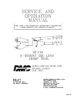
Содержание HC134
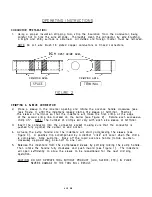
Страница 26: ...PORT ON SEE NOTE p SIDE E 1 6...