

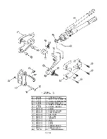


4. Tig hten jam screw 6 1 securely onto adjustment screw 8.
5. Reassemble the tool by reversing the order of operation described in
steps 1 through 4 in ADJ USTING PU MP SYSTEM PRESSURE.
6. To assemble remainder of pump, follow steps 1 th rough 9 in
REPLACING OIL PLUNGER.
"I
tim,p, �
1
I
I 1--n-----<f)-
1 1
"""1n
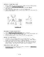
PRESSURE
FIGURE 1 0
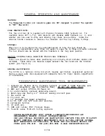
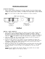
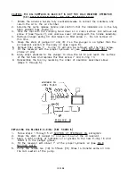
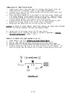
ADJUSTMENT OF PUMP SYSTEM PRESSURE:
1 . Adjusting the system pressure requires a DMC HPG1 Pressure Gauge.
2. Screw the HPG- 1 Gauge onto the gauge adapter 45 located on the bottom
side of the pump (see Figure 1 0) .
CAUTION: HAND TIGHTEN GAUGE TO THE PUM P ADAPTO R ONLY! DO NOT OVERTIG HTEN!
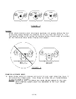
3. Place a connector in the indenter area and perform a crimp. Observe the needle
position when th e pump clicks and release is hea rd. The needle should be in
the ·GREEN" area of the ga uge.
4. If adjustment is needed, follow steps 1 through 7 of ADDITION OF HYDRAU LIC
_QlL
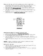
5. Hold the pump in a vertical position with the oil reservoir u p, remove loc king
screw 6 1 and tighten adjusting screw 8 to raise the pressure or loosen screw 8
to lower the press ure.
6. Replace locking screw 6 1 and follow steps 8 through 10 of ADDITON OF
HYDRAU LIC OIL.
12 OF 2S
Содержание HC134
Страница 26: ...PORT ON SEE NOTE p SIDE E 1 6...