


CAUTION : THE OIL SUPPLIED IN EACH KIT IS NOT FOR COLD WEATHE R OPERATIO N
(S[ E COLD WEAT H ER NOTE). DO NOT US[ BRAK[ rLUID!
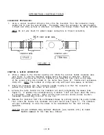
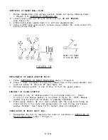
1. Rotate the advance han dle fully counterclockwise to retract the in denters and
return the oil to the oil chamber.
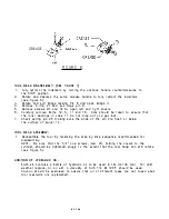
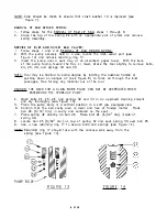
2. Actuate the pump release handle and confirm that the indenters are in the fully
open position (see Fig ure 1 ).
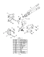
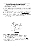
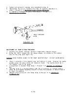
3. Hold the tool with the crimping head down on a clean surface and remove set
screw 2 (see Figure 7), and unscrew cover 40 along with the handle assembly.
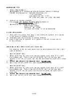
4. Remove plunger spring 30 and loosen oil filler screw 7. Do not remove at
this time.
5. G rasp the stem of plunger 47 and lift it so the FJlun ger is no higher than the
oil reservoir section of the body 37 ( see Fig ure 8).
6. Remove filler screw 7. 0-ring 1.3 will also be removed with the filler screw.
7. Fill the reservoir with the proper hydraulic oil (see COLD WEATH ER NOTE for
choice of oils) .
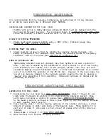
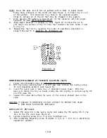
8. Apply slight pressure to the plunger to allow the oil to just reach the surface
of the full hole and replace the filler screw 7 and 0-ring 1 3.
9. Reassem ble the tool by reversing the order of operation described a bove
(steps 3 through 5).
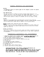
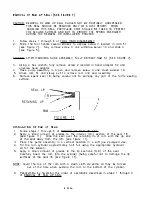
MAXI M U M
OI L
LEVEL FLUSH
FIG URE 8
REPLACING OIL PLU NGER 0 - RI NG: (SEE FIGURE 8)
Q
1. Follow ste ps 1 throu gh 5 of ADDITION OF HYDRAU LIC OIL paragraph.
2. Grasp the stem of plunger 47 and pull it out of the oil reservoir.
3. Apply a light coating of hydraulic oil or grease to the new 0-ring 1 6 and
install it in the plunger groove.
4. Fill the reservoir with about 1" of the proper hydraulic oil (see CO LD
WEATHER NOTE).
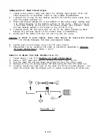
5. Pump the handle ten (1 D) to fifteen (15) times to transfer some oil into
the ram section of the pu mp.
1 D O F 2B
Содержание HC134
Страница 26: ...PORT ON SEE NOTE p SIDE E 1 6...