


VersaGateway User’s Manual
Document #: 2015006.1.pdf
PAGE 23 of 44
Divelbiss Corporation • 9778 Mt. Gilead Road • Fredericktown, Ohio 43019 • 1-800-245-2327 • www.divelbiss.com
Device Features
INSTALLING WI-FI IN EZ LADDER TOOLKIT
For Wi-Fi supporting models of VersaGateway, EZ LADDER Toolkit (PLC on a Chip) utilize the Wi-Fi connection as an Ethernet con
-
nection.
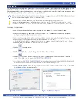
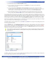
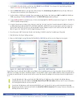
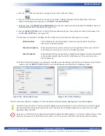
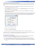
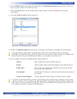
To use Wi-Fi, the Ethernet option must be configured in the Bootloader and EZ LADDER Toolkit (Project Settings). Refer to
the
Ethernet Port
Section of this manual. Follow the instructions for installing Ethernet in the Bootloader and Project
Settings of EZ LADDER Toolkit as shown.
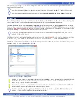
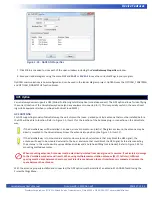
With the antenna properly installed and Ethernet installed (Bootloader and Project Settings), the Wi-Fi connection may now be
used as a Programming Port, Modbus TCP port or for VersaCloud M2M Connectivity. To use the Wi-Fi Port as Modbus TCP or for
VersaCloud M2M Connectivity, additional configuration is required.
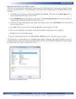
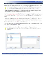
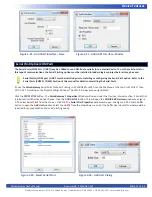
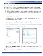
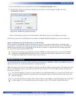
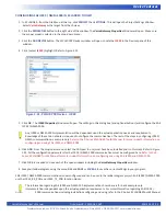
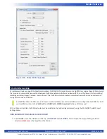
In addition to configuring the Wi-Fi in the Bootloader, the SSID and Password will need to be entered to make the
connection. These items are configured in EZ LADDER Toolkit, when connected to the target in the Monitor Mode. Refer to
the Wi-Fi section of the P-Series EZ LADDER Toolkit for selecting the Wi-Fi network, setting SSID and entering the password.
To configure Modbus TCP for use over Wi-Fi, see the
Modbus TCP Section
of this manual.
To configure VersaCloud M2M Connectivity over Wi-Fi, see the
VersaCloud M2M Connectivity Section
of this manual.
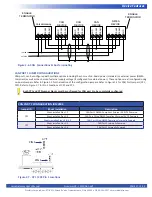
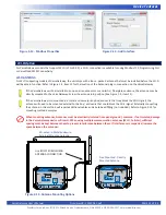
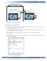
Serial Ports- COM 2 / COM 3
The VersaGateway includes two general purpose RS232/RS485 Serial Ports (COM2 and COM3). These port are each individually
configurable as either RS232 or RS485 and are used for general communications including Modbus Master, Modbus Slave or com
-
munications to other devices using customized drivers (structured Text). Refer to Figure 1-5 (COM2 - Item 9, COM3 - Item 10) for
the location of the serial ports terminal blocks. Refer to the P-Series EZ LADDER Toolkit Manual for details regarding supported baud
rates and structured text functions.
The serial ports must be configured using on-board jumpers to select the type of each serial port (RS232 or RS485). Since
the actual terminal blocks pin functions depend on the configurations of the serial ports, they should be configured first.
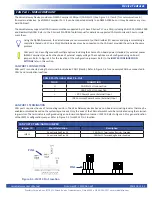
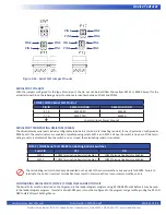
SERIAL PORT JUMPER CONFIGURATIONS
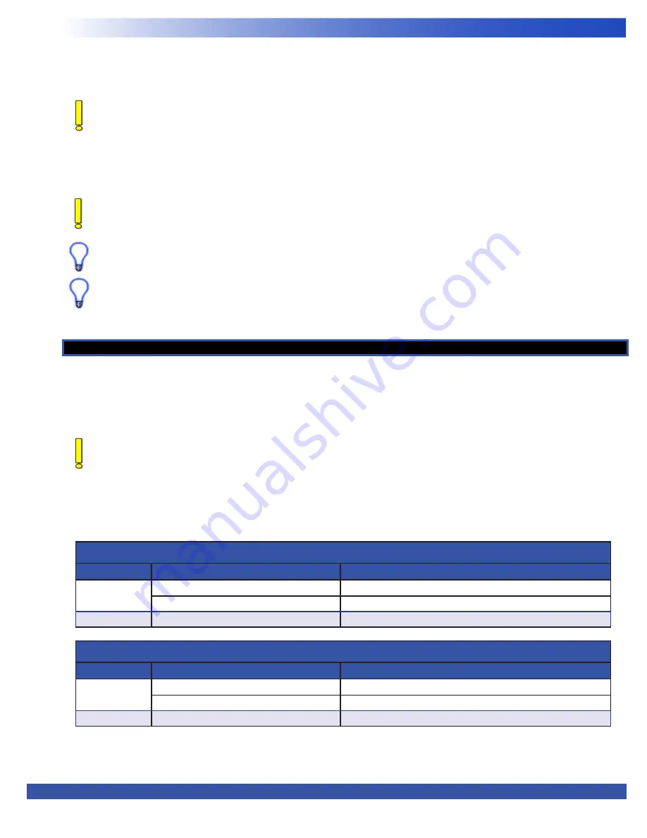
Each serial port (COM2 / COM3) may be individually configured as RS232 or RS485. To configure the type of serial port(s), jumpers
P11, P12 and P17 must be configured.
Refer to Figure 1-5 for the general location of the configuration jumpers. Refer to Figure 2-16 for the pin-outs for the jumpers.
COM2 CONFIGURATION JUMPERS
Jumper ID
RS232
RS485
P11
Shunt installed Pins 1-3
Shunt installed Pins 3-5
Shunt installed Pins 2-4
Shunt installed Pins 4-6
P17
Shunt installed Pins 1-3
Shunt installed Pins 3-5
COM3 CONFIGURATION JUMPERS
Jumper ID
RS232
RS485
P12
Shunt installed Pins 1-3
Shunt installed Pins 3-5
Shunt installed Pins 2-4
Shunt installed Pins 4-6
P17
Shunt installed Pins 2-4
Shunt installed Pins 4-6


