VersaGateway User’s Manual
Document #: 2015006.1.pdf
PAGE 38 of 44
Divelbiss Corporation • 9778 Mt. Gilead Road • Fredericktown, Ohio 43019 • 1-800-245-2327 • www.divelbiss.com
Device Features
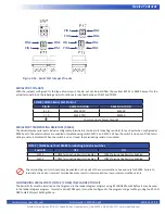
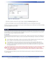
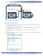
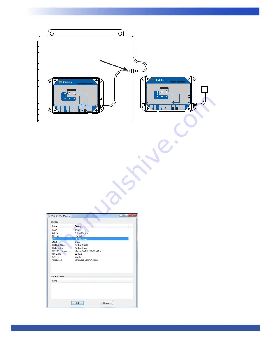
Figure 2-35 -Antenna Mounting Options
VersaCloud M2M Solutions
VersaGateway
CORPORATION
WIFI ANT
I4
I5
I2
I3
I1
STS
PWR
SYSTEM
SD
CARD
+
GPS ANT
CELL
ANT
PWR
IN
+-
PGM
AUX
PWR
IN
CAN
H L
0
CAN
H L
1
-
COM
COM
2
3
ETHERNET
R/B : RS232 RX
RS485 B
T/A : RS232 TX
RS485 A
: GND
Terminals
COM 2/3
R
B
T
A
R T
B A
VersaCloud M2M Solutions
VersaGateway
CORPORATION
WIFI ANT
I4
I5
I2
I3
I1
STS
PWR
SYSTEM
SD
CARD
+
GPS ANT
CELL
ANT
PWR
IN
+-
PGM
AUX
PWR
IN
CAN
H L
0
CAN
H L
1
-
COM
COM
2
3
ETHERNET
R/B : RS232 RX
RS485 B
T/A : RS232 TX
RS485 A
: GND
Terminals
COM 2/3
R
B
T
A
R T
B A
Mounted in Metal Enclosure -
External Mounted Antenna
Free Mounted - Directly
Mounted Antenna
Use ISOLATED BULKHEAD
ANTENNA CONNECTION
CONFIGURING GPS IN EZ LADDER TOOLKIT
1. In EZ LADDER, from the File Menu at the top, click
PROJECT
then
SETTINGS
. This will open the Project Settings Window.
Select
VersaGateway
as the target from the choices.
2. Click the
PROPERTIES
button to the right side of the window. The
VersaGateway Properties
Window will open. Make sure
the proper model is selected in the drop-down menu.
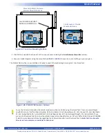
3. Click the
ADD DEVICE
button. The
PLCHIP-PXX Devices
window will open. Locate the
GPS
in the Devices pane
of this window.
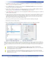
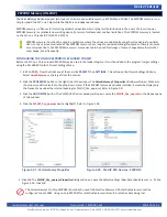
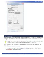
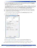
4. Click / select
GPS
(highlight). Refer to Figure 2-36. Click
OK
. The GPS Properties window will open identifying UART4 as the
interface for the GPS. Click
OK
.
Figure 2-36 - PLCHIP-PXX Devices - GPS

