VersaGateway User’s Manual
Document #: 2015006.1.pdf
PAGE 26 of 44
Divelbiss Corporation • 9778 Mt. Gilead Road • Fredericktown, Ohio 43019 • 1-800-245-2327 • www.divelbiss.com
Device Features
Modbus Master or Slave may be utilized with the Serial Ports (UARTs / COM ports). To use Modbus Master or Slave over Serial
Ports, Modbus Master/Slave must be installed and configured in the ladder diagram project.
Serial Port(s) (COM port / UART must be installed prior to installing or configuring the Modbus Master / Slave using
Serial. Refer to the Serial Ports (COM2 / COM3) Section of this manual for details on installing the Serial Ports.
T
o use the
VersaGateway
Serial Ports
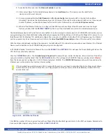
for Modbus, in EZ LADDER Toolkit, from the File Menu at the top, click
PROJECT
then
SET
-
TINGS
. This will open the Project Settings Window. The VCG-X-X-X was previously selected
Click the
PROPERTIES
button. The
VersaGateway’s Properties
Window will open. Under the Devices,
Internal
section, if Modbus
Master or Slave is installed, it will be listed. Click the
ADD DEVICE
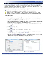
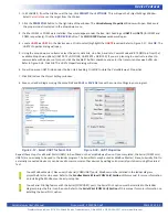
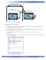
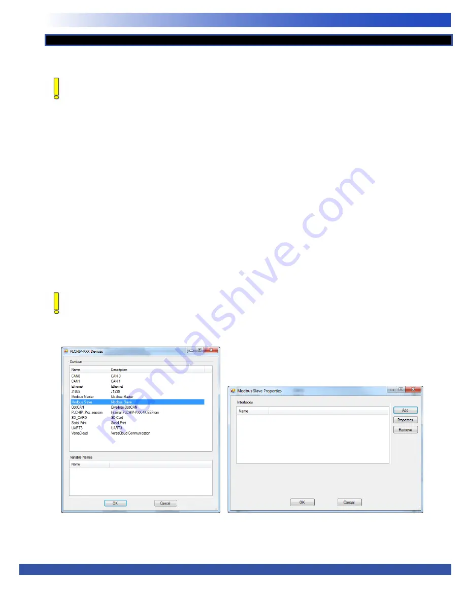
button. This will open the
PLCHIP-PXX Devices
window. See Figure
2-19. Select
Modbus Master
or
Modbus Slave
from the choices. Click
OK.
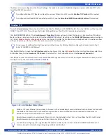
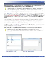
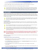
The
Modbus Slave or Modbus Master Properties
window
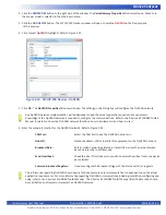
will open depending on the type of Modbus port you selected. See Figure 2-20. Click the
ADD
button to open the
Add Interface
window.
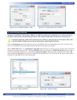
For Modbus Slave, see Figure 2-21. Select
UART#
from the Interface Drop-down select box. Set the
Slave ID #.
This should be the
network ID for this VersaGateway on the Modbus network. Select
RTU
as the type and leave the other fields as default set.
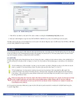
For Modbus Master, see Figure 2-22. Select
UART#
from the Interface Drop-down select box. Set the
Response Timeout(ms).
This
should delay time for a slave to respond in milliseconds. Select
RTU
as the type.
Click
OK
the number of times required to save the Modbus Settings and return to the EDIT workspace. Remember to Save your lad
-
der diagram using the menu
FILE
and
SAVE
or
SAVE AS.
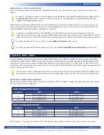
Modbus Master / Slave is now installed and configured to use in the ladder diagram program on the VersaGateway Device.
For detailed information on how to configure variables and use Modbus in EZ LADDER Toolkit, refer to the
P-Series EZ LADDER Toolkit Manual It contains information how to use Modbus Master and Slave using variables and
function blocks.
Modbus Master / Slave (COM Port)
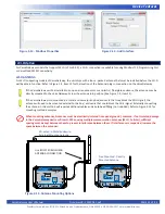
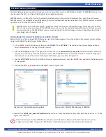
Figure 2-19 - Selecting Modbus
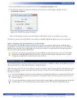
Figure 2-20 - Modbus Properties


