VersaGateway User’s Manual
Document #: 2015006.1.pdf
PAGE 21 of 44
Divelbiss Corporation • 9778 Mt. Gilead Road • Fredericktown, Ohio 43019 • 1-800-245-2327 • www.divelbiss.com
Device Features
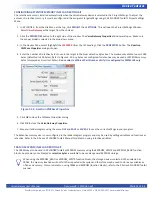
T
o use the
VersaGateway
Ethernet port or Wi-Fi connection
for Modbus, in EZ LADDER Toolkit, from the File Menu at the top, click
PROJECT
then
SETTINGS
. This will open the Project Settings Window. The VCG-X-X-X was previously selected.
Click the
PROPERTIES
button. The
VersaGateway’s Properties
Window will open. Under the Devices,
Internal
section, if Modbus
Master or Slave is installed, it will be listed. Click the
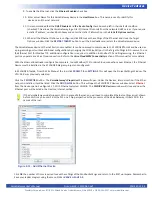
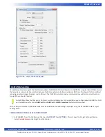
ADD DEVICE
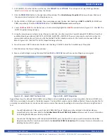
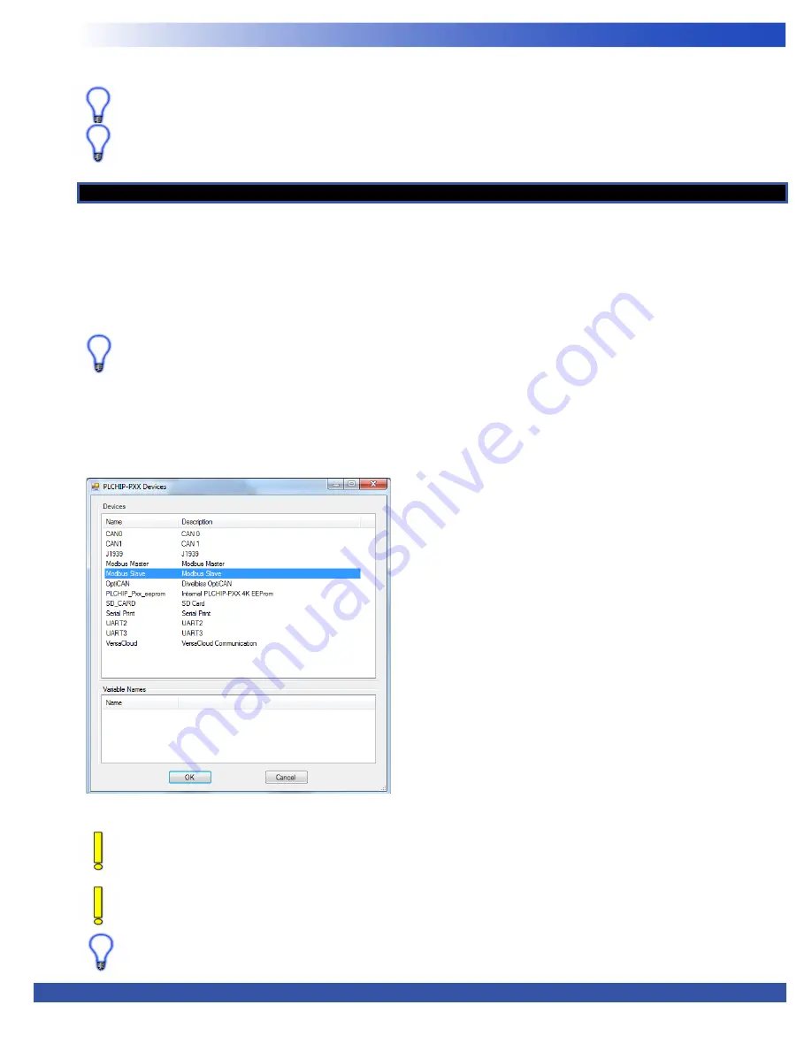
button. This will open the
PLCHIP-PXX Devices
window. See Figure
2-12. Select
Modbus Master
or
Modbus Slave
from the choices. Click
OK.
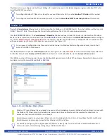
The Modbus Slave or Modbus Master Properties window
will open depending on the type of Modbus port you selected. See Figure 2-13.
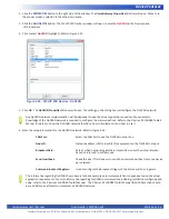
For purposes of configuration, the Slave option will be shown. For Modbus Master configuration details, refer to the P-
Series EZ LADDER Toolkit Manual
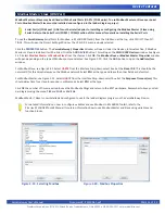
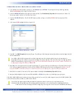
Click the
ADD
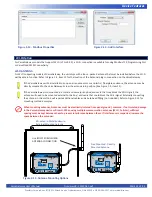
button to open the
Add Interface
window. See Figure 2-14. Select
Ethernet
from the Interface Drop-down select box.
For Modbus Slave, Set the
Number of TCP Sockets
. The default is 1. For Modbus Master, set the
Response Timeout
(ms).
Click
OK
the number of times required to save the Modbus Settings and return to the EDIT workspace. Remember to Save your lad
-
der diagram using the menu
FILE
and
SAVE
or
SAVE AS.
Modbus TCP
Figure 2-12 - Add Modbus Master/Slave
The Ethernet is now configured in the Project Settings. It is ready to be used in the ladder diagram program as Modbus TCP or for
VersaCloud M2M Connectivity.
To configure Modbus TCP (Master or Slave) for use over Ethernet or Wi-Fi, see the
Modbus TCP Section
of this manual.
To configure VersaCloud M2M Connectivity over Wi-Fi, see the
VersaCloud M2M Connectivity Section
of this manual.
VersaGateway models can only support Ethernet or Wi-Fi individually. As the PLC on a Chip utilizes the Wi-Fi as Ethernet,
VersaGateways can only support one of either Ethernet or Wi-Fi at a time.
Modbus TCP (over Ethernet) is now ready to be used on the VersaGatway. Several additional function blocks are used with
the Modbus TCP Ethernet port in the ladder diagram project. More on Modbus and the required function blocks is
detailed in the P-Series EZ LADDER User’s Manual.
For details on configuring and using Modbus TCP (Master or Slave), refer to the P-Series EZ LADDER Toolkit Manual. It
contains in-depth information regarding using variables and Modbus.


