VersaGateway User’s Manual
Document #: 2015006.1.pdf
PAGE 39 of 44
Divelbiss Corporation • 9778 Mt. Gilead Road • Fredericktown, Ohio 43019 • 1-800-245-2327 • www.divelbiss.com
Device Features
Cellular Data Option
The VersaGateway optionally supports an internal Cellular Data Modem (model dependent). This internal cellular data option is
designed to operate with the Divelbiss VersaCloud M2M Portal. The purpose of the cellular data feature is to allow for remote re
-
porting, control and configuration of equipment in areas that may not have adequate communications avenues such as broadband
(Ethernet or Wi-Fi). This cellular data option provides a communications path to the Divelbiss VersaCloud M2M portals (CLOUD) via
nationwide cellular coverage.
The Cellular Data option requires cellular data coverage from Divelbiss Corporation. Monthly fees and data usage charges
apply. As data fees apply, consideration should be made during the application ladder diagram program development to
limit the amount and size of data to only what is required to reduce cost.
CELLULAR ANTENNA
For Cellular connection supporting models of VersaGateway, the unit ships with a loose - packed antenna that must be installed
before the Cellular connection will be able to function. Refer to Figure 1-5, Item 14 for the location of the Antenna plug-in connec
-
tion on the VersaGateway.
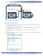
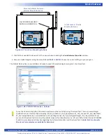
If the VersaGateway will be installed in an open-air environment or an plastic / fiberglass enclosure, the antenna may be
directly mounted to the VersaGateway. Screw the antenna into position (See Figure 1-5, Item 14).
If the VersaGateway is to mounted in a metal enclosure (or any box/enclosure that may block the Cellular signal), the
antenna will need to be mounted external to the box / enclosure that could block the Cellular signal. Externally connecting
the antenna in this method will require additional cables and a bulk-head fitting (not included). Refer to Figure 2-37 for
mounting method examples.
When mounting antennas, Antennas must be electrically isolated from panel ground / common. If not isolated, damage
to the VersaGateway device will result. When using multiple communication antennas (Wi-Fi, Cellular), sufficient
spacing must be kept between them to prevent interference between them. If interference is suspected, increase the
space between the antennas.
With the antenna properly installed and connected, the Cellular Data option must be installed / enabled in EZ LADDER Toolkit using
the Project Settings Menu.
CONFIGURING CELLULAR DATA IN EZ LADDER TOOLKIT
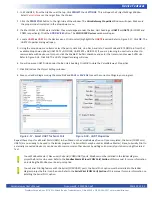
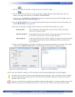
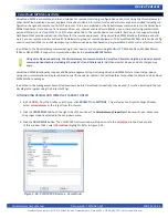
1. In EZ LADDER, from the File Menu at the top, click
PROJECT
then
SETTINGS
. This will open the Project Settings Window.
Select
VersaGateway
as the target from the choices.
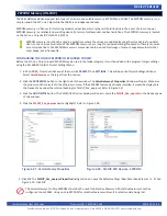
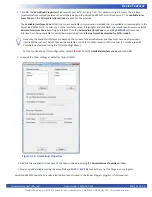
2. Click the
PROPERTIES
button to the right side of the window. The
VersaGateway Properties
Window will open. Make sure
the proper model is selected in the drop-down menu.
3. Click the
ADD DEVICE
button. The
PLCHIP-PXX Devices
window will open. Locate the
Cellular
in the Devices pane
of this window.
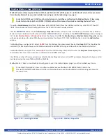
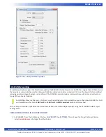
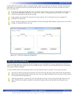
4. Click / select
Cellular
(highlight). Refer to Figure 2-38. Click
OK
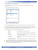
. The GPS Properties window will open identifying UART1 as the
interface for the Cellular Modem. Click
OK
.
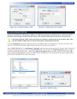
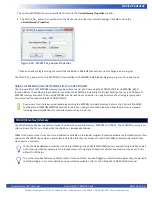
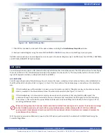
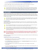
5. Click
OK
to as needed to close each of the open windows including the
VersaGateway Properties
window.
6. Save your ladder diagram using the menu
FILE
and
SAVE
or
SAVE AS
to save the current settings in your program.
The GPS option is now installed and ready to used in the ladder diagram program / structured text.
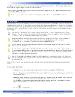
To use the GPS option to identify location and other information, it must be accessed via Structured Text. Several Target
specific structured text functions are used: EZ_GPS_GetDateTimeUTC, EZ_GPS_GetMovement, EZ_GPS_GetPosition and
EZ_GPS_GetPrecision. Refer to the P-Series EZ LADDER Toolkit Manual for details on how these target specifics function,
how to use GPS and using Structured Text.
GPS functionality Structured text examples are available for download
.

