


©
2005
Directed Electronics, Inc.
21
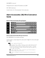
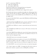
where: H1 – primary harness (VIPER 3000)
H2 – auxiliary harness (VIPER 3000)
H3 – door lock harness (VIPER 3000)
The H3/A, H3/D and H3/G pins on the door lock harness must be grounded.
The H1/3 pin must be connected to the VIPER 3000 siren.
The “Light flash” jumper of the VIPER 3000 must be configured in the (-) position.
If the “Fuel door release” function is not available on the installed car (no “Fuel door release” button
on driver’s door) then CH6 can be dedicated to “Headlight” function and N3/4 (BROWN) from
CANIM may be connected to H2/4 (GRAY/BLACK) on the VIPER 3000. In this case CH6 may
be configured as latch.
If a remote start module (VALET 561T) is connected with VIPER 3000 and CANIM the following
connections may be made:
- The H1/10 pin (CH3) from VIPER 3000 must be connected to pin H1/4 from remote start
module. In this case CH3 on VIPER 3000 must be configured for remote start.
- N4/2 (BLUE) from CANIM must be connected to 4-pin satellite harness pin1 from remote start
module.
- N4/3 (LT. BROWN) from CANIM must be connected to H2/3 (remote start harness) from
remote start module.
- N4/1 ( VIOLET/WHITE ) from CANIM must be connected to H2/2 (remote start harness) from
remote start module. If this wire is used then the remote start module must be learned to read
tachometer input wire during engine running.
- H1/8 (BLACK) from the remote start module must be grounded.
- H1/9 (WHITE) from the remote start module can be connected to N1/4 (WHITE/BROWN –
turn signals) from CANIM. (or N3/4 (TAN - headlight) if not used with a channel on VIPER
3000). The “Light flash” jumper of the remote start module must be configured in the (-) position.
- H2/1 (BLACK/WHITE – remote start harness) from the remote start module must be grounded.
- Pin 1 “Output to ignition circuit” (PINK) – heavy gauge relay satellite from the remote start
module must be connected to to ignition wire in the car (Finding Wires in the Vehicle).