


©
2005
Directed Electronics, Inc.
13
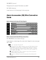
N3/7 RED/WHITE (-) trunk release input
Connect this wire to the “(-) 200mA Channel 2 output” of the security system.
NOTE: After a valid activation of this input, the CAN-IM will activate it’s “Trunk Status Output” in order to
prevent the security system from triggering, in case that the trunk is not automatically released or opened
by the user. This output will remain active as long as the trunk remains opened. If the trunk is not opened
this output will remain active a predefined time (usually 2 minutes, but no more than 3 minutes), to simu-
late the factory auto-relock feature, or until a disarm/unlock or arm/lock input is received on the corre-
sponding inputs or read on the CAN bus.
➤
➤
During the time-out for the auto-relock feature or while the trunk is opened the CAN-IM will ignore
other trunk release commands received on this input or read on the CAN bus.
➤
➤
If the trunk release input is activated while the car is disarmed/unlocked the “Trunk Status Output”
will not be grounded artificially. Also there will be no time-out for the auto-relock feature because this
feature will be disabled in this case.
➤
➤
This input will not be valid during the execution time of an arm/lock or disarm/unlock command.
However, a valid activation of this input will end a comfort closure in progress after an arm/lock.
Remote Start (N4) Wire Connection Guide
Remote Start Harness Wiring Diagram
___
___
___
Remote Start Harness Wiring Instructions
N4/1 VIOLET/WHITE RPM (Tachometer) output
Connect this wire to “Tachometer Input wire” of the remote start module.
N
NO
OTTEE:: This output is active only during remote start.
N4/2 BLUE (-) remote start status input
Connect this wire to the “Status Output” of the remote start module.
NOTE: As long as this input is active the CAN-IM will:
➤
➤
Monitor the engine speed (RPM) and activate RPM output.
BROWN
(+) remote start shutdown output
BLUE
(-) Remote start status input
VIOLET/WHITE
RPM (Tachometer) output
N4/1
N4/2
N4/3