Directed Install Essentials CAN1 Скачать руководство пользователя страница 11

©

2005 

Directed Electronics, Inc.

11

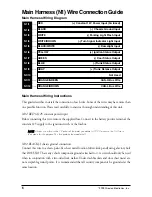
N2/6 BROWN (-) not used

This input must not be connected. The function is not available.

N2/7 GRAY (-) hood status

Connect this wire to the “(-) hood pin input” of the security system.

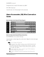
Alarm Accessories (N3) Wire Connection
Guide

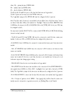
Alarm Accessories Harness Wiring Diagram

___

___

___

___

___

___

___

Alarm Accessories Harness Wiring Instructions

N3/1 WHITE/BLUE (-) front windows down input

Connect this wire to a channel output of the security system. Configure the security system output
type as “validity” .

N

NO

OTTEE:: This input is only valid with the ignition OFF.

If a short pulse (less than 1-second) is received on this input, and CAN-IM finds any of the front 

windows above the “small vent” position, it will roll down the front window(s) to the “small vent” 
position, else if it finds any of the front windows above the “large vent” position, it will roll down 
the front window(s) to the “large vent” position. In any other case the input will be ignored. In no 
case the windows will be  rolled up.

If a long pulse (greater than 1-second) is received on this input, CAN-IM will roll down the 

front window(s) as long as the input remains active.

This input is not valid during the execution of the comfort closure function after an arm/lock 

command.

RED/WHITE

(-) Trunk release input

ORANGE/BLACK

(-) Radio input

GRAY/BLACK

(-) Fuel door release input

BROWN

(-) Headlight input

VIOLET/BLACK

(-) Sunroof input

WHITE/BLACK

(-) Rear windows down input

WHITE/BLUE

(-) Front windows down input

N3/1

N3/2

N3/3

N3/4

N3/5

N3/6

N3/7

Содержание Install Essentials CAN1

Страница 1: ...k B Bu us s I In nt te er rf fa ac ce e I In ns st ta al ll la at ti io on n G Gu ui id de e NOTE This product is intended for installation by a professional installer only Any attempt to install thi...

Страница 2: ...hicle Recovery System VRS and Warn Away are all Trademarks or Registered Trademarks of Directed Electronics Inc w ww ww w d di ir re ec ct te ec ch hs s c co om m D Di ir re ec ct tF Fa ax x 8 80 00 0...

Страница 3: ...ec ct ti io on n G Gu ui id de e 1 13 3 Remote Start Harness Wiring Diagram 13 Remote Start Harness Wiring Instructions 13 C Cl li if ff fn ne et t N N5 5 W Wi ir re e C Co on nn ne ec ct ti io on n...

Страница 4: ...dule is applicable for the following vehicles Vehicle Year s Audi A3 2004 up A4 2004 up A6 2004 up Skoda Octavia II 2004 up Seat Altea 2004 up Leon 2006 up Toledo 2005 up Volkswagen Caddy 2004 up Golf...

Страница 5: ...2005 Directed Electronics Inc 5 CAN1 Module Features and Interface N5 CLIFFNET LED N6 ESP2 SW1 N1 CAN J1 JUMPER N4 REMOTE START N3 ALARM ACCESSORIES N2 D L CLIFFNET IS NOT SUPPORTED AT THIS TIME...

Страница 6: ...purpose This fuse protects the module itself N1 2 BLACK chassis ground connection Connect this wire to a clean paint free sheet metal location driver kick panel using a factory bolt that DOES NOT have...

Страница 7: ...n Ignition is enabled In this case CAN IM will ignore a valid arm lock input and will automatically flash the turn signals rapidly 100 msec on 100 msec off for 5 seconds to notify the user N1 5 BLACK...

Страница 8: ...efined time usually 2 min utes but no more than 3 minutes to simulate the factory auto relock future or until a disarm unlock or arm lock command is received on the analog inputs or read on the CAN bu...

Страница 9: ...e the CAN IM will ignore the Turn Signal input Moreover the CAN IM will send back the disarm unlock command to alarm unit through the ESP or Cliffnet buses If a door or trunk is opened and this input...

Страница 10: ...t be activated with ignition ON then the comfort closure function will be implemented by the CAN IM after this output is activated If a comfort closure function is in progress this output will not be...

Страница 11: ...CAN IM finds any of the front windows above the small vent position it will roll down the front window s to the small vent position else if it finds any of the front windows above the large vent posit...

Страница 12: ...t activation feature or to the Light Flash wire of the remote start module Configure this as a negative output from that system N3 5 GRAY BLACK fuel door release input Connect this wire to a channel o...

Страница 13: ...the CAN bus If the trunk release input is activated while the car is disarmed unlocked the Trunk Status Output will not be grounded artificially Also there will be no time out for the auto relock feat...

Страница 14: ...ot brake ON Reverse ON Car speed 0 Hand brake not active N4 3 BROWN remote start shutdown output Connect this wire to a positive shutdown input wire such as the Brake Switch or Reverse Backup Shutdown...

Страница 15: ...t is not triggered Activate deactivate panic on the alarm unit when the panic button on the original factory remote control is pressed This connector is also used to program the alarm unit with the Bi...

Страница 16: ...tected on the ARM LOCK input The CAN IM will close all windows and doors included in the factory comfort closure feature Comfort closure will monitor the windows position and close all openings comple...

Страница 17: ...seconds and then extinguish the LED this is an unusual occurrence Checks if the platform of the car is recognized max 3 sec if not illuminate the LED red for 2 5 sec and then extinguish the LED Waits...

Страница 18: ...nder the fuses box T28 5 for CAN L and T28 4 for CAN H Under the steering column connector T20d 15 J527 for CAN L and connector T20d 14 J527 for CAN H In case that a Directed remote start module is us...

Страница 19: ...module Channel 2 for Trunk release function Channel 3 for remote start N NO OT TE E If a remote start module is not needed this channel can be used for Headlight ON OFF func tion Channel 4 for Front w...

Страница 20: ...utput N1 10 N1 11 ORANGE GREEN CAN H N1 12 ORANGE BROWN CAN L N2 1 GREEN BLACK H3 C Arm Lock N2 2 BLUE BLACK H3 F Disarm Unlock N2 3 BLUE H2 1 Disarm Unlock all doors N2 4 GREEN WHITE Arm Output N2 5...

Страница 21: ...case CH3 on VIPER 3000 must be configured for remote start N4 2 BLUE from CANIM must be connected to 4 pin satellite harness pin1 from remote start module N4 3 LT BROWN from CANIM must be connected to...

Страница 22: ...nt 12V input RED heavy gauge relay satellite from the remote start module must be connected to 12V permanent in the car 12V in the key switch The rest of the wires from the remote start module can be...

Страница 23: ...n Status Output YELLOW N1 Remote Start Status Input BLUE Remote Start Shutdown Output BROWN RPM Tachometer Output VIOLET WHITE Disarm Unlock Driver s Door Input BLUE BLACK Disarm Unlock All Doors Inpu...

Отзывы: