Dickey-John INTELLIAG AI-120 Скачать руководство пользователя страница 112

OPERATOR’S MANUAL

AI-120 Virtual Terminal

11001-1606E-201703 Rev B

MAIN OPERATOR SCREEN / 105
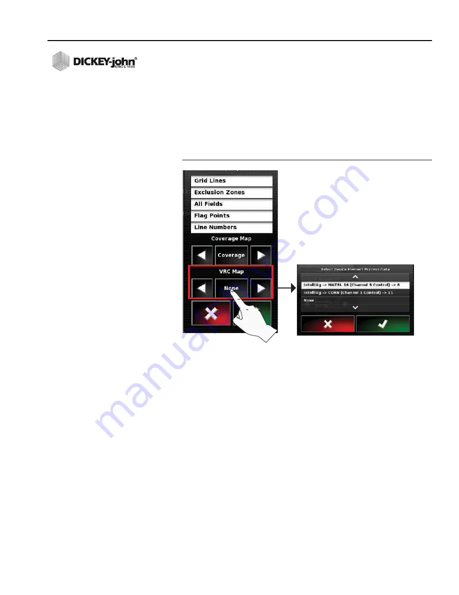
VRC MAP COVERAGE

Select a variable rate map when using a variable rate prescription map 
through task controller.

1. Press the 

VRC Map 

button to open the Select Device Element window 

or press the left/right arrows to scroll through the selections.

2. Select the desired variable rate map and press the 

OK

 button to 

accept.

Figure 155
VRC Map Coverage

Содержание INTELLIAG AI-120

Страница 1: ...INTELLIAG AI 120 ISO VIRTUAL TERMINAL Operator s Manual SINCE 1966...

Страница 2: ...nits 21 Dry Product Volume 21 Dry Density 22 Liquid Product Units 22 Application Rate Product Type 22 Lightbar Setup 23 Enable Disable Terminal Lightbar 24 LED Spacing 24 LED Mode 24 Environment Setup...

Страница 3: ...Isobus 58 Vehicle Options 61 New Vehicle Profile 61 Vehicle Geometry 63 Load an Existing Vehicle Profile 63 Implement Profile 64 Load an Existing Implement Profile 68 Implement Geometry 68 Multiple Bo...

Страница 4: ...overage 103 VRC Map Coverage 105 Grid Lines 106 Exclusion Zones 106 All Fields 107 Flag Points 108 AB Line Numbers 108 Boundary and Exclusion Zone Buttons 109 Exclusion Zone 109 Flag Point 109 Guideli...

Страница 5: ...132 Boundary Offset 133 Clear a Boundary 134 Create an As Applied Job 135 Select an Existing Job 136 Customize an As Applied Job Detail Record 137 Headlands 138 Variable Rate Job Setup 141 Initial Imp...

Страница 6: ...bration 170 Auto Steering Performance 173 Pre Operating Checklist 173 Approaching the Guideline 173 Auto Steering Engage 173 Auto Steering Disengage 174 Limitations 174 Remote Assistance 175 Terminal...

Страница 7: ...OPERATOR S MANUAL AI 120 Virtual Terminal 11001 1606E 201703 Rev B VI...

Страница 8: ...the word WARNING indicates a potentially hazardous situation which if not avoided could result in death or serious injury Use of the word CAUTION with the Safety Alert Symbol indicates a potentially h...

Страница 9: ...OPERATOR S MANUAL AI 120 Virtual Terminal 11001 1606E 201703 Rev B 2 SAFETY NOTICES...

Страница 10: ...des simple icon based setup Safety warnings must be acknowledged at every power cycle and when the system is refreshed It is important to read and understand the safety requirements prior to operation...

Страница 11: ...OPERATOR S MANUAL AI 120 Virtual Terminal 11001 1606E 201703 Rev B 4 INTRODUCTION...

Страница 12: ...n Attaching Bracket to Terminal 1 Secure bracket to tractor using using the 4 SAE screws included 2 Loosen the wing nut on the bracket and remove the ball mount plate 3 Remove the 3 hex nuts on the ba...

Страница 13: ...al Terminal 11001 1606E 201703 Rev B 6 INSTALLATION TERMINAL CONNECTIONS 1 Power On Off 2 Reset 3 Connection to the tractor cab harness 4 Rear USB port 5 LAN RJ45 not used 6 Side USB port Figure 2 Ter...

Страница 14: ...SMB and harness are required for interfacing with shutoff modules Tru Count solenoid modules are not supplied by DICKEY john Harnessing structure illustrated below Figure 3 AI 120 Harnessing Battery S...

Страница 15: ...OPERATOR S MANUAL AI 120 Virtual Terminal 11001 1606E 201703 Rev B 8 INSTALLATION...

Страница 16: ...utton and should only be used in this instance Press and hold the Reset button for approximately 3 seconds to begin reboot A reset during normal operations may cause active files not to save and lead...

Страница 17: ...with the vehicle icon visible onscreen If it is not visible a GPS signal may not be detected A No GPS warning will appear onscreen if a valid signal is not found and will not activate until a signal...

Страница 18: ...e and Release PRESS AND RELEASE This is the most common movement and is primarily used for pressing buttons and selecting menus This movement involves applying finger press on the touchscreen and then...

Страница 19: ...ase Example LED LIGHT INDICATORS The terminal is equipped with LED s that provide status for Battery status Supply status Autosteering accuracy Light sensor Status LED s flash as the system powers on...

Страница 20: ...s LED Colors Figure 10 Power Supply LED Colors Figure 11 Autosteering LED Colors Battery fully charged Battery partly charged Battery flat Charging flashing Good supply Low supply Very low supply or o...

Страница 21: ...OPERATOR S MANUAL AI 120 Virtual Terminal 11001 1606E 201703 Rev B 14 USING THE TERMINAL...

Страница 22: ...System options Vehicle setup Implement setup To display the Setup Menu 1 At the Main Operate screen press the Setup button to display the Setup menu Figure 12 Setup Menu USER SETUP At the Setup menu...

Страница 23: ...ent language displays on the Language button Press the Language button to open the language window 3 Select the desired language and press the Check button to accept Figure 13 Language Setup DECIMAL P...

Страница 24: ...the Time Date setup menu Three selections adjust the date format time format and current time Figure 15 Time and Date Setup 2 Press the Date Format button and select the format preference Press the C...

Страница 25: ...INAL SETUP Figure 17 Time Format 4 Press the Current Time button to open the keypad and type in the desired time 12 hour format Press the Check button to accept NOTE The and buttons increase decrease...

Страница 26: ...ections allow adjustment of settings based on region units measurements latitude longitude pressure area dry product dry density liquid and application rate increment type Figure 19 Units Setup UNITS...

Страница 27: ...e Longitude button and select standard decimal format or DMS decimal minute second and press the Check button to accept Figure 21 Latitude Longitude Setup PRESSURE UNITS 4 At the Regional Units menu p...

Страница 28: ...tton and select the area units as ha hectare or ac acre and press the Check button to accept Figure 23 Area Units DRY PRODUCT VOLUME 6 At the Regional Unit menu press the Dry Product Volume button for...

Страница 29: ...el Press the Check button to accept Figure 25 Dry Density LIQUID PRODUCT UNITS 8 At the Regional Units menu press the Liquid Products Units button and select the liquid units as gallons cubic feet or...

Страница 30: ...LIGHTBAR SETUP A lightbar at the top of the terminal visually indicates the position of vehicle center from the center of a guideline using GPS coordinates Figure 28 Terminal Lightbar 1 Press the Ligh...

Страница 31: ...he LED Spacing button and enter the desired spacing Press the Check button to accept Figure 31 LED Spacing LED MODE 4 Two LED mode options allow selection of how the lights respond when turning toward...

Страница 32: ...d includes the following parameters Audio volume Button clicks Alarm audio Touchscreen calibration Touchscreen sensitivity Screen shot and creating global home screens System 150 file transfer Auto st...

Страница 33: ...reases volume in increments of 10 decreases volume in increments of 10 0 volume mutes all sounds from the console Figure 34 Audio Volume BUTTON CLICKS 3 An audible button click can be enabled or disab...

Страница 34: ...een button re calibrates the display when screen responsiveness does not occur effectively to a finger touch Follow onscreen instructions to perform a calibration 1 At the Environment setup screen pre...

Страница 35: ...ress the Touchscreen Sensitivity button A system reboot is required after calibration is complete Press the Check button to proceed Figure 39 Touch Screen Sensitivity 2 At the Calibration screen selec...

Страница 36: ...tton Press the Check button to accept the desired selection Figure 41 Screen Shot Take Screen Shot The Screen Shot function captures a picture of the screen as it appears on the display and is saved t...

Страница 37: ...Multiple global home screens can be saved and retrieved by manually selecting or by toggling through the saved screens NOTE To select how a Global Home screen is selected refer to Global Home Screen M...

Страница 38: ...4 To save the home screen with the selected applications and dashboard items press the Save Home Screen button Figure 44 Manage Global Home Screens 5 Enter a desired name using the virtual keyboard a...

Страница 39: ...gure 44 GLOBAL HOME SCREEN MODE Selection of Global Home Screens can be accomplished via manual selection or by scrolling To Select Global Home Screen Mode 1 At the Environment Setup screen press the...

Страница 40: ...TEM 150 FILE TRANSFERS This functionality transfers files from a Topcon 150 system to newer models Contact DICKEY john Technical Support at 1 800 637 3302 for assistance AUTO STEERING STATUS WINDOW Th...

Страница 41: ...6E 201703 Rev B 34 TERMINAL SETUP TOOLBAR BUTTON SIZE Button sizes on the left side of the Home screen can be adjusted to appear in small medium or large sizes Select the desired size and press the Ch...

Страница 42: ...line length To adjust Map settings 1 Press the User Map icons to open the Map Options setup menu Figure 50 Map Options Setup POINT OF FOCUS The focal point of the vehicle icon can be set to either the...

Страница 43: ...ions Press the Check button to accept selection Enabled activates the panning function on the guidance screen Disabled deactivates the panning function on the guidance screen When enabled an icon appe...

Страница 44: ...utton to display menu selections Press the Check button to accept selection Enabled displays the loaded coverage map as yellow and new coverage mapping displays as green Disabled displays the loaded c...

Страница 45: ...plement Figure 56 Pause Boundary Recording with Master Figure 57 Recording a Boundary With Coverage VISUAL REFERENCE LINE LENGTH The tractor symbol has an optional reference line that is user defined...

Страница 46: ...OPERATOR S MANUAL AI 120 Virtual Terminal 11001 1606E 201703 Rev B TERMINAL SETUP 39 Figure 59 Visual Reference Line Length...

Страница 47: ...A software upgrade should not be necessary when receiving a new console and is typically performed when a new upgrade is required PROVISION USB UPGRADE 1 On a Windows machine unzip the installation ZI...

Страница 48: ...e USB flash drive and the console restarts automatically 12 After the restart the console displays the touch screen calibration screen Touch the displayed cross marks in turn and then press Confirm or...

Страница 49: ...TUP The Console menu enables applications that are compatible with the virtual terminal To adjust console settings 1 Press System Features Console icons to display the Console Features menu The Select...

Страница 50: ...task files variable rate prescription from a USB device and to export as applied data to a USB device IMPORTANT File server should never be disabled Figure 64 File Server CAMERAS 1 Press the Camera b...

Страница 51: ...con Take note of the Console Identifier number listed on the Registration Key box This number will be provided by the representative supplying the registration key code 3 Press the Registration Key1 b...

Страница 52: ...3 300 Mbps Wireless N USB adapter is required for wireless capability to properly operate No similar models can be substituted Refer to the Remote Assistance section for setup instructions NOTE The re...

Страница 53: ...ionality Figure 70 Guidance Screen REVERSE DETECTION non Topcon GPS Receivers only Reverse Detection performs an implement to tractor alignment that automatically forces the implement to position itse...

Страница 54: ...asks in a typical job This may be useful when learning to use the terminal Enabling the option places a new icon at the top right of the Operation screen Selecting the icon displays the help screen As...

Страница 55: ...he selection menu 2 Select to highlight Job Assist or Quick Start 3 Press the Check button to accept QUICK START SETTINGS The Quick Start Settings menu is used to define what functions will use the Qu...

Страница 56: ...s not appear in the Quick Start steps it is not enabled at the Quick Start Settings menu i e Record Boundary in Figure 74 1 Press the Quick Start button The first task enabled at the Quick Start Setti...

Страница 57: ...ISO implements controlled through the IntelliAg terminal Figure 76 Implement Screen AUTO SECTION CONTROL Auto Section Control is an automated row shutoff system that automatically shuts off individua...

Страница 58: ...when a prescription map is loaded 1 Press the Variable Rate Control button to open selection menu Select Enabled when variable rate is used Select Disabled when variable rate is not used Figure 78 Va...

Страница 59: ...s Verify the following GPS inputs to enable a valid GPS signal GPS receiver Output Radar The Guidance screen indicates the current status of the GPS signal refer to Figure 82 To Verify GPS Input 1 At...

Страница 60: ...creen 2 Select Enabled and press the Check button to accept 3 The Baud Rate setting is set the same on the terminal and the receiver A minimum setting of 19 200 is required for 5 Hz GPS receivers The...

Страница 61: ...Virtual Terminal 11001 1606E 201703 Rev B 54 TERMINAL SETUP Figure 82 Guidance Screen with GPS Status RADAR OUTPUT 1 Radar output settings are only applicable when using a Topcon receiver Figure 83 R...

Страница 62: ...erial port 2 if in use Xlinks is on serial port 3 if in use or on serial port 2 if NMEA GPS out is not in use Figure 84 GPS Serial Port ALARMS The General Alarm Setup menu lists the standard alarms th...

Страница 63: ...t the first distance from the boundary edge has been reached to begin slowing down the vehicle and soon take control The distance is measured from the tractor to the boundary along the AB line Second...

Страница 64: ...o the AI 120 terminal ASC10 ECU FIRMWARE MISMATCH not applicable to IntelliAg VT HIGH PRIORITY A high priority alarm indicates a system performance error has been detected that could potentially effec...

Страница 65: ...Point Preset and apply the desired icon and re name if desired 3 Press the Check button to confirm the selection Figure 87 Flag Point Presets ISOBUS The IsoBus menu allows setup and customization of t...

Страница 66: ...default terminal connected to the working set master If the UT client doesn t appear on the correct UT reconfigure the UT number appropriately If there is a conflict the following message will appear...

Страница 67: ...desired soft keys to display on the Work screen and press the Check button to accept Figure 90 Soft Keys Per Column SOFT KEY LOCATION The default soft key location is on the right side of the main Wor...

Страница 68: ...ehicle setup consists of the following Selecting or creating a new vehicle profile Entry of vehicle geometric measurements NEW VEHICLE PROFILE A preloaded list of vehicle makes and models are availabl...

Страница 69: ...OPERATOR S MANUAL AI 120 Virtual Terminal 11001 1606E 201703 Rev B 62 TERMINAL SETUP Figure 93 New Vehicle Profile 1 2 4 3 5...

Страница 70: ...iver E GPS Height distance from ground to GPS receiver F Axle Height distance from back axle center to ground To enter vehicle measurements 1 Press the Vehicle Geometry icons to open the Geometry menu...

Страница 71: ...ed or started Load a New Custom Implement Profile 1 At the Setup Menu screen press the Implement New Custom icons 2 Select the appropriate implement style in the upper window from the 4 selections Rig...

Страница 72: ...press the Implement box that displays the default name 5 Use the keyboard to create a new implement name 6 Press the keyboard Check button to accept 7 The new name appears in the New Implement window...

Страница 73: ...lect ISOBUS as the ECU type that is performing section or application rate control Press the Check button to accept 12 Press the Next button to proceed Figure 98 Implement Control Type 13 Select the f...

Страница 74: ...OPERATOR S MANUAL AI 120 Virtual Terminal 11001 1606E 201703 Rev B TERMINAL SETUP 67 Figure 99 New Implement Setup 13 14 15 16...

Страница 75: ...anter control channel in the field Configuring an implement identifies the type of implement attached how much area the implement covers and any implement offset IMPORTANT It is critical to enter the...

Страница 76: ...t allowed at this screen Figure 101 Adding Implement Dimensions MULTIPLE BOOMS If the implement has multiple booms the boom used for guidance must be selected from the BOOM FOR GUIDANCE selection list...

Страница 77: ...nction on the ECU Setup screen is modified When changing from a variable rate job to a manual as applied rate job Loading a software update to modules connected to the CAN Bus To Adjust Implement Sett...

Страница 78: ...in the IntelliAg application via the Import Export Config button Refer to the IntelliAg manual 1 At the Setup screen press the Implement ECU icons 2 Press the Firmware Version button to begin process...

Страница 79: ...essing buttons or turning system off 9 When the final Load Firmware screen indicates 100 completion the system must restart Press the Check button to begin restart An additional upload screen appears...

Страница 80: ...the ECU Setup screen Figure 103 IMPORTANT After the reboot is complete and startup screens have displayed Figure 5 it is recommended to cycle power by turning off the ignition switch Wait approximatel...

Страница 81: ...wn Pressure Load cell modules down pressure Prod MA WSMT WSMT2 modules except planter module Prod Output Module Planter or boom section out modules Prod Planter WSMT Planter WSMT2 only Prod Planter WS...

Страница 82: ...120 terminal INTELLIAG PDC SETUP The following IntelliAg PDC screens must be configured to perform Auto Section Control functions via the AI 120 terminal Control channel setup assigning number of rows...

Страница 83: ...Enter the number of solenoid outputs connected to the specific TCOM Outputs do NOT always total the number of clutches but the total number of controlled solenoids The Output Numbers s value is autom...

Страница 84: ...WITCHES The Clutch Set screen identifies what switches on the row shutoff switch box enable and disable planter sections or outputs 1 At the Clutch Configuration screen press the Clutch Set button Ent...

Страница 85: ...Corresponding row shutoff switches will turn sections on and off Figure 110 Module Output Assignment IMPLEMENT SECTION CHECK IMPORTANT After clutch row assignment it is recommended to perform a diagn...

Страница 86: ...the row shutoff switch box enable and disable planter sections or outputs Up to 24 sections automatically populate to the Sections menu as configured in the IntelliAg system NOTE Section and width cha...

Страница 87: ...output modules and switch modules and does not apply to Section Control by Channel Delay times vary based on manufacturer Refer to Figure 112 for recommended clutch delay times Delay time defaults for...

Страница 88: ...ETUP 81 Figure 113 On Time Off Time SWITCH BOX SETUP Switch Box Setup defines how the virtual switch box on the main guidance screen is used to control sections 1 At the System menu screen press the I...

Страница 89: ...he number of switches on the virtual switch box The maximum number of switches allowed up to 12 is based on the number of sections entered at the Section Setup menu Example 3 switches is the maximum n...

Страница 90: ...OPERATOR S MANUAL AI 120 Virtual Terminal 11001 1606E 201703 Rev B AUTO SECTION CONTROL SETUP 83 Figure 116 Switch Assignment 1 2 3...

Страница 91: ...ntrol Section Control by Channel is disabled by selecting Rate Control only 3 At the Main Menu open the Auto Section Control window and select to turn off channels by Avoiding gaps turns off the chann...

Страница 92: ...hen used with the DICKEY john AI 120 terminal No further action required The master switch is located at bottom right corner of the guidance screen to turn sections on and off Figure 119 Master Switch...

Страница 93: ...is only visible if the active implement is an ISOBUS implement When enabled the GPS speed can be used in lieu of using a radar to detect speed Figure 121 GPS Speed Emulation Setup PRODUCT SETUP IMPORT...

Страница 94: ...reas Application bar Toolbar Dashboard Figure 123 Main Operator s Screen APPLICATION BAR BUTTONS The application bar consists of all active applications loaded on the console Pressing the respective b...

Страница 95: ...displays on the main guidance screen Figure 125 Guidance Window GPS BUTTON The GPS window displays vehicle position orientation and GPS accuracy by selecting the respective tab GPS POSITION GPS Positi...

Страница 96: ...left right tipping of the vehicle off the center axis Pitch Measurement of the forward backward tipping of the vehicle off the center axis Figure 127 Vehicle Orientation Window GPS ACCURACY The number...

Страница 97: ...e MEMORY USAGE Main Memory indicates the percentage amount of internal console memory that has been used USB Memory indicates the percentage amount of memory used on an inserted USB device File system...

Страница 98: ...1606E 201703 Rev B MAIN OPERATOR SCREEN 91 TROUBLE CODES Trouble codes provides a list of errors identified during system operation Figure 131 Trouble Codes Window LOGGING Logs data captured during au...

Страница 99: ...tings Job notes JOB STATISTICS Amount of area covered remaining area to be covered and the distance traveled during a job is displayed Figure 133 Job Statistics Window JOB DURATION Total job hours tot...

Страница 100: ...r the current job Figure 135 Job Settings Window GUIDANCE SETTINGS File names of the current guideline vehicle and implement display in the window for the current job Figure 136 Guidance Settings Wind...

Страница 101: ...ontrol section for setup instructions and Auto Section Control Dashboard for operation instruction Figure 138 Auto Section Control SWITCH BOX The Virtual Switch Box button displays a window to manuall...

Страница 102: ...display Figure 140 IntelliAg Window INVENTORY MANAGER BUTTON The Inventory Manager button displays all files loaded on the console Files are arranged by category and can be edited deleted exported and...

Страница 103: ...om of the Inventory Manager screen perform 4 global file options Select deselect files Delete file Edit file name Export file View files that are saved to USB device verify that a successful backup oc...

Страница 104: ...sion buttons VIEWING PERSPECTIVE BUTTONS Viewing buttons adjust the appearance of the guidance screen The 5 perspective views include Zoom In Zoom Out Perspective View Overhead View North Up View ZOOM...

Страница 105: ...e View button places the map into virtual perspective with a virtual horizon Figure 144 Perspective View OVERHEAD VIEW In Overhead View the top of the screen represents the vehicle s current direction...

Страница 106: ...e map view is limited to the surrounding area around the vehicle Map panning allows viewing of the surrounding area without the need to drive to that location Map panning is enabled by dragging a fing...

Страница 107: ...ance screen by hiding or displaying map layers Map Layer Types Grid Lines Exclusion Zones All Fields Flag Points Line Numbers Press the respective map layer item to toggle between enable white and dis...

Страница 108: ...ality map provides a visual representation of GPS position accuracy for areas covered in coverage mapping This layer displays even if the coverage layer is turned off Press the center of the legend to...

Страница 109: ...v B 102 MAIN OPERATOR SCREEN Figure 150 GPS Quality COVERAGE MAP When the master switch and implement sections are on coverage displays on the map as green during product application This layer is hid...

Страница 110: ...relative to the color gradients selected To Adjust Color Variance of Map 1 At the Map Layers and Coverage Map window use the left and right arrow buttons to select the desired applied rate map Figure...

Страница 111: ...OPERATOR S MANUAL AI 120 Virtual Terminal 11001 1606E 201703 Rev B 104 MAIN OPERATOR SCREEN Figure 154 Applied Rate Adjustment 1 2 3 4...

Страница 112: ...variable rate map when using a variable rate prescription map through task controller 1 Press the VRC Map button to open the Select Device Element window or press the left right arrows to scroll throu...

Страница 113: ...gitudinal and latitudinal lines of the earth and provide a visual aid of the vehicle s orientation Figure 156 Grid Lines EXCLUSION ZONES Exclusion zones can be created in the system or imported from a...

Страница 114: ...tual Terminal 11001 1606E 201703 Rev B MAIN OPERATOR SCREEN 107 ALL FIELDS When enabled the All Fields layer shows other field boundaries in the same farm in a white outline on the guidance screen Fig...

Страница 115: ...re 159 Flag Points AB LINE NUMBERS After recording a boundary and the initial AB line is established all passes in the field are automatically numbered Line numbers display positive or negative based...

Страница 116: ...oundaries section for boundary creation Figure 161 Boundary and Exclusion Zone Buttons EXCLUSION ZONE The Exclusion Zone button is used when importing a shape file configured to have exclusion zones A...

Страница 117: ...tton functions 1 Steering Tune adjustment 2 Steering checklist 3 Compass and mounting bias calibration Figure 163 Steering Calibration NUDGE BUTTONS Nudge buttons shift the position of a guideline Gui...

Страница 118: ...the IntelliAg master switch The virtual master switch on the AI 120 terminal only controls swath control AUTOSTEERING BUTTONS Autosteering functionality must be enabled at the Setup screen for the Au...

Страница 119: ...the Job Assist popup window Press any of the toolbar buttons on the right side of the display and the job Assist window will provide definition of the button function Figure 167 Job Assist Menu DASHB...

Страница 120: ...etected by the system Color indicates GPS signal quality VEHICLE GROUND SPEED Displays current vehicle ground speed SWATH NUMBER Displays the current guideline row number For example driving along the...

Страница 121: ...on screen to aid in button functionality when the Help button is pressed Selecting an item that has a help icon opens an identifying description of that item Access to the specific function is tempora...

Страница 122: ...ve the DICKEY john logo to open the Global Home screen menu The Screen Shot button is located above the DICKEY john logo Screen shot functionality when enabled captures an image as it appears on the s...

Страница 123: ...OPERATOR S MANUAL AI 120 Virtual Terminal 11001 1606E 201703 Rev B 116 MAIN OPERATOR SCREEN...

Страница 124: ...hese guidelines can be saved and reused CREATE A GUIDELINE The procedure for creating a guideline is the same for all guideline types 1 Press the Guideline button to select the guideline type 2 Press...

Страница 125: ...set the A point 2 Turn on the master switch optional press the A point button and drive vehicle towards the desired B point Figure 172 Set A Point 3 Select the B point button to set B A straight red l...

Страница 126: ...Figure 174 Manual AB Lines PIVOTS Once sufficient data is gathered from creating one lap a circular guideline displays onscreen The size of the circles change based on the vehicle s distance from the...

Страница 127: ...button to turn on coverage mapping and start driving along a pivot curve The vehicle curve must be maintained until the pivot accuracy bar is full Figure 176 Drive Pivot Curve With Coverage Mapping 5...

Страница 128: ...OPERATOR S MANUAL AI 120 Virtual Terminal 11001 1606E 201703 Rev B GUIDELINES 121 Figure 177 Complete Coverage Map...

Страница 129: ...created for the curve and auto steering is enabled 2 Select the Guideline menu button and press the Identical Curve button 3 Activate coverage mapping set the A point and start driving the identical c...

Страница 130: ...or steering along coverage that was treated earlier that a curve was not created and saved This guideline method is also referred to as free form To Enable Guidelock 1 Apply coverage and start drivin...

Страница 131: ...OPERATOR S MANUAL AI 120 Virtual Terminal 11001 1606E 201703 Rev B 124 GUIDELINES...

Страница 132: ...to appear on the screen CREATE A CLIENT FARM FIELD 1 Press the Field Menu button 2 Press the New Field button to setup a new field profile For a previously created field press the Select Field button...

Страница 133: ...11001 1606E 201703 Rev B 126 AS APPLIED JOB SETUP Figure 181 Enter Client Name SMITH 3 4 5 6 7 Imports field information via USB Select the nearest field Current GPS position is used and only works if...

Страница 134: ...closed Pause Recording button shuts off recording of boundary until the Record Field Boundary button is pressed to start recording again Press the Pause button if an obstacle prevents driving on the b...

Страница 135: ...dary can be recalled for use in a new job IMPORTANT A saved field boundary has GPS coordinates based on the location of the actual field Therefore the vehicle needs to be near the actual field for the...

Страница 136: ...e or the boundary will be defined from the first shape in the file which may not represent that boundary needed Import a Shapefile 1 Load the shapefile to the USB 2 Insert the USB into the virtual ter...

Страница 137: ...area The Exclusion Zone button and Boundary button are similar with the difference being yellow identifying exclusion and blue identifying blue 4 Drive around the perimeter of the exclusion zone unti...

Страница 138: ...file name 4 Press the Check button to recall Figure 188 Recall an Exclusion Zone CREATE FLAG POINTS 1 Drive to the desired location to mark with a flag point 2 Select the Field menu button 3 Press th...

Страница 139: ...difies the icon representing the flag point Rename Renames a flag point Delete Permanently deletes the selected flag point from the field Clear All Permanently clears all flag points in the field GPS...

Страница 140: ...et 1 Select the Field menu button 2 Press the Boundary Offset button The boundary offset default is set to 0 3 Enter a value for the desired boundary offset using the virtual keypad and press the Chec...

Страница 141: ...CLEAR A BOUNDARY The Clear Boundary button erases a boundary from the field To Clear a Boundary 1 Select Field menu 2 Press the Clear button 3 Press Yes to acknowledge and remove the boundary Clearing...

Страница 142: ...ame by pressing the Check button or Select Job Name to enter a custom name using the keypad Figure 194 Create Job Name 4 After creating a job name the master switch onscreen will change from red to gr...

Страница 143: ...field 1 Before selecting an existing job verify the correct field is selected 2 Press the Job Menu button 3 Press the Select Job button 4 At the Select Job Window press the Client or Farm tab to view...

Страница 144: ...ered and exported as part of the job report relating to weather crop and product Any manually entered details defined appears on the front page of the job report as a Job Summary Add Job Details 1 Pre...

Страница 145: ...adland if needed and press the Check button to accept This is useful to supply a buffer zone for steering if the headland width is set so that the tip of the implement would be touching the fence If a...

Страница 146: ...st to the zoom level as specified on this screen when approaching a headland during coverage mapping 10 Press the Check button to accept changes 11 Press the Alarm button to set headland alarm setting...

Страница 147: ...e field boundary The distance between the 2 lines is the configurable headland width measured in multiples of the implement working width swaths Figure 201 Headlands Example The screen automatically z...

Страница 148: ...INITIAL IMPORT OF JOB DATA Any new data for import to the terminal from a farm management software tool requires the following steps before transfer to a USB memory device Farm Management Software Re...

Страница 149: ...name if additional maps are transferred separately Renaming the TASKDATA folder for additional file transfers avoids overwrite of existing maps stored on the terminal that reside in the TASKDATA folde...

Страница 150: ...menu to import a task 1 Insert USB memory device into USB port on the side of terminal 2 Press the Job Menu button 3 Press the Data Exchange button 4 Select the Import Task Data button 5 At the Import...

Страница 151: ...xists on the USB and list taskdata xml files that are found If this method is not successful the USB can be browsed manually to select the required file Once a file is selected it is possible to chang...

Страница 152: ...open Select Task window 3 Select the desired task to load that appear in the Task column All tasks imported appear in this task column 4 Press the Check button to accept selected task Figure 207 Sele...

Страница 153: ...vices Multiple filters can be selected and a window will open for each filter that is chosen To Select Filters 1 Press the Filters button 2 Press to highlight all desired filters to display onscreen 3...

Страница 154: ...Press the Check button to accept Figure 210 Sorting Tasks EDITING TASK DATA FILES Imported task data files can be edited if needed 1 Press the Task Data Menu button 2 Press the Edit Task Data button T...

Страница 155: ...t the Target Element titled IntelliAg to open the device element choices 5 Select the appropriate device element 6 Press the Check button to accept 7 Follow the same steps 3 7 to assign a control targ...

Страница 156: ...RIPTION VALUES The Edit button allows fixed values to be set for the prescription Default value is sent to the ECU when the task is started If there is no variable rate prescription this is the only r...

Страница 157: ...es a new prescription by either setting the fixed values or importing a shapefile to allow variable rate control Once the prescription is created select the Default button in the Source column To Crea...

Страница 158: ...OPERATOR S MANUAL AI 120 Virtual Terminal 11001 1606E 201703 Rev B VARIABLE RATE JOB SETUP 151 Figure 215 Create New Prescription 1 2 3...

Страница 159: ...OPERATOR S MANUAL AI 120 Virtual Terminal 11001 1606E 201703 Rev B 152 VARIABLE RATE JOB SETUP...

Страница 160: ...ous job data cleared before starting a new job TIP Enable the Quick Start feature or the Job Assist feature at the Settings System Features Guidance menus to help with stepping through job setup TO BE...

Страница 161: ...types of task totals stored is dictated by the connected ECU A task must be started at least once for any totals to display 1 Press the Task Totals button to open the Task Totals window 2 Press the Ch...

Страница 162: ...nually start and stop tasks regardless of the master switch state Manually or master switch start and stop tasks both manually and via master switch 3 Press the Check button to accept Figure 220 Start...

Страница 163: ...Implement master switch must be off to export an As Applied job As Applied job coverage details are exported to a pdf file to create a job report To Export an As Applied job 1 Insert USB memory device...

Страница 164: ...the job A job report automatically includes Job name Start and end date Total area covered Total completion hours Total hours coverage mapping is active Distance covered Boundary name Boundary area T...

Страница 165: ...Rev B 158 OPERATION Figure 224 Job Report Example NOTE Data contained within the job summary only appears as manually entered at the Record Job window There is no data transfer from IntelliAg for prod...

Страница 166: ...OPERATOR S MANUAL AI 120 Virtual Terminal 11001 1606E 201703 Rev B OPERATION 159...

Страница 167: ...lect the type of file to export and press the Check button to accept CSV files Shape files 7 Press the Export Mode button to select what happens to data after export and press the Check button to acce...

Страница 168: ...and off without turning the master switch off The switch box can have a maximum of 12 switches and can be turned on or off by pressing the switches labeled 1 through 12 Each switch controls one or mo...

Страница 169: ...age mapping When the master switch is off the virtual switch box or a physical switch will not control sections On the main guidance screen the master switch has two states On green Off red When the m...

Страница 170: ...163 VIRTUAL SWITCH BOX AUTO SECTION EXAMPLES Implement sections are enabled and disabled using either the virtual switch box or the implement dashboard Figure 229 Master Switch On Sections 1 and 2 On...

Страница 171: ...k auto section adjustments during operation Figure 232 Auto Section Control Window CONTROL MODE Control Mode Slider adjusts the maximum and minimum limits of gaps and overlaps 1 5 setting increases ga...

Страница 172: ...bles auto section control with a button press SELECT BOOM FOR SECTION CONTROL If different materials are assigned to multiple channels a popup window displays before operation to select which material...

Страница 173: ...OPERATOR S MANUAL AI 120 Virtual Terminal 11001 1606E 201703 Rev B 166 USING THE GUIDANCE SCREEN...

Страница 174: ...eiver software update ENABLE AUTO STEERING 1 From the Main screen press the Setup button to display the Setup menu 2 At the Setup menu press the System icon and the Features icon to 3 Press the Auto S...

Страница 175: ...teering Calibration Menu COMPASS CALIBRATION To Perform a Compass Calibration 2 Press the Calibration button to open the wizard Follow onscreen instructions and press the Next button to proceed to the...

Страница 176: ...allel mounting to the roof and fixed tilt of cab with respect to chassis The calibration ensures the role angle measurement is accurate with respect to the vehicle contact with the ground so that roll...

Страница 177: ...stem stays within the vehicle and implement safe turning capabilities This setting prevents the accidental occurrence of extremely sharp turns when autosteering is enabled 9 Sensitivity is an AES 25 e...

Страница 178: ...OPERATOR S MANUAL AI 120 Virtual Terminal 11001 1606E 201703 Rev B AUTO STEERING CALIBRATION 171 Figure 239 Steering Tuning Window 6 7 8 9 10 11...

Страница 179: ...OPERATOR S MANUAL AI 120 Virtual Terminal 11001 1606E 201703 Rev B 172 AUTO STEERING CALIBRATION...

Страница 180: ...ng the desired direction to auto steer It is recommended that vehicle speed is slow so that overshooting the line does not occur It is not necessary to be exactly on the guideline moving in the exact...

Страница 181: ...ment can also occur due to a non console input such as losing satellites or losing the guideline LIMITATIONS Manual control of the vehicle is required to perform sharp turns including U turns and 90 d...

Страница 182: ...USB adapter NOTE A NetGear N150 Wireless USB Adapter or TP Link TL WN821Nv3 Wireless USB Adapter is required for wireless to properly operate No similar models can be substituted These adapters are a...

Страница 183: ...iPhone 4 and 5 Samsung S S2 S3 Activating Remote Assistance 1 Enable the Remote Assistance feature at the Settings menu System Features Console 2 When Remote Assistance is enabled a Wizard automatical...

Страница 184: ...w view and navigate the terminal Remote Assistance Step 4 Please wait for the Remote Assistance window to start with Ready to connect Record the values for Your ID 3 space separated number when intern...

Страница 185: ...terminal DOWNLOAD TEAMVIEWER SOFTWARE 1 Go to www teamviewer com 2 Press the Green Download button to initiate download 3 When download is completed and the TeamViewer Setup window appears select the...

Страница 186: ...r or the master switch The terminal must be connected to the internet via ethernet or wireless access point via a USB wi fi adapter If there is no accessible internet but a network connection is avail...

Страница 187: ...inal 11001 1606E 201703 Rev B 180 REMOTE ASSISTANCE If no internet is available when starting the TeamViewer wizard a re direct to the Wi Fi wizard connects to a hot spot or wireless access point Figu...

Страница 188: ...l not start and the LED s will flash together for 10 seconds before turning off Battery is below 7 0 volts The console will not start and the LED s will flash together for 10 seconds before turning of...

Страница 189: ...ional Satellite Augmentation system Omnistar VBS Uses Omnistar Virtual Base Station VBS Omnistar XP Uses Omnistar XP correction high accuracy Ominstar HP Uses Omnistar HP correction very high accuracy...

Страница 190: ...ected the icon color changes vary depending on the correction source it is picking up at the time When correction source is selected DGPS WAAS EGNOS MSAS VBS button is green otherwise button is red XP...

Страница 191: ...rts First part signifies the file is a job Second part represents the file creation date Third part indicates the time of file creation The time used is in a 24 hour clock format 0000 represents 12 00...

Страница 192: ...Curve Guidance pattern IMPORTANT Typically curves are selected for the first and second lap AB lines are selected and this guidance pattern is used to complete the coverage of the remaining field Thi...

Страница 193: ...of the USB flash drive 2 Navigate to the USB flash drive and double click on the file install_mbr cmd 3 After install safely eject the USB flash drive from the computer 4 Verify that the terminal is...

Страница 194: ...ial damages Said part will not be considered defective if it substantially fulfills the performance expectations THE FOREGOING WARRANTY IS EXCLUSIVE AND IN LIEU OF ALL OTHER WARRANTIES OF MERCHANTABIL...

Страница 195: ...1 1606E 201703 Rev B Operator s Manual 5200 Dickey john Road Auburn IL 62615 www dickey john com 217 438 3371 217 438 6012 fax 2017 DICKEY john DICKEY john Sales 800 637 2952 agsales dickey john com D...

Отзывы: