32
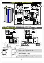
CONNECTING THE PRESSURE SENSOR
U
V
W
1
2
Ø V
+24V dc
2
1
POWER
SUPPLY
FAN
OUTPUT
Ø V
+24V dc
MOTOR
N
.O
.
C
4
3
2
1
INPUT
OUTPUT
C
N
.C
.
PRESS .SENS.
3
2
1
+
V
dc
4
- 2
0m
A
0
- 4
,5
V
Ø
V
Fl
ow
N
.O
.
Fl
ow
C
4 5
FLOW SENS.
LINE
R
S
T
ØV
D-
D+
ØV
D-
D+
RS485
-
Wire the
pressure sensor
cables to terminals
PRESS SENS
for SENSOR 4-20 mA
for SENSOR 0,5 – 4,5 V
PRESS .SENS.
3
2
1
+
V
dc
4
- 2
0m
A
0
- 4
,5
V
Ø
V
Fl
ow
N
.O
.
Fl
ow
C
4 5
FLOW SENS.
PRESS .SENS.
3
2
1
+
V
dc
4
- 2
0m
A
0
- 4
,5
V
Ø
V
Fl
ow
N
.O
.
Fl
ow
C
4 5
FLOW SENS.
Configuration of
the jumpers
JP1 JP2
JP1
Vdc = 5 V
Vdc = 24 V (factory set)
JP2
Sensor signal
0,5 – 4,5 V
Sensor signal
4–20 mA
(factory set)
+ Vdc
(PIN1)
4-20 mA
(PIN2)
0-4,5V
+
-
ground
ground

