background image

6-3 Default Screen 


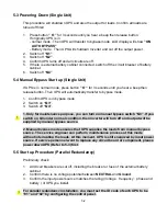
After UPS starts up and completes the self-test, screen will show: 


ON AUTO BYPASS

LOAD UNPROTECTED


BYPA.

MAINS

!

ON AUTO BYPASS

LOAD UNPROTECTED


BYPA.

MAINS

!


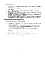
1. When any event occurs, you will see the sign “!” flashes. You can press “

j

” to see 

the details. For example :


K

O

N

Q

E

R

F

/

T

L

O

V

N

I

A

M

N

I

A

M

T

U

P

N

I

K

C

E

H

C

K

O

N

Q

E

R

F

/

T

L

O

V

T

U

P

N

I

K

C

E

H

C

N

I

A

M

N

I

A

M


Press “

j

” again will go to the next message. If there is no further message, then the 

screen will back to default screen.   


2. Press “ESC” at any time will back to default screen.


6-3


Содержание NH-15k

Страница 1: ...Uninterruptible Power Supply 3PHASE NH SERIES...

Страница 2: ...gle 2 1 2 3 Reserve Mode Single 2 2 2 4 Bypass Mode Single 2 3 2 5 Normal Mode Parallel 2 4 2 6 Backup Mode Parallel 2 5 2 7 Reserve Mode Parallel 2 6 2 8 Bypass Mode Parallel 2 7 2 9 Hot Standby Redu...

Страница 3: ...2 Positioning 4 3 4 5 3 Environment 4 4 4 6 Wiring 4 5 4 6 1 Preparations 4 5 4 6 2 Wiring Single 4 5 4 6 3 Wiring Parallel Redundancy Single Input 4 9 4 6 4 Wiring Parallel Redundancy Dual Input 4 10...

Страница 4: ...3 Powering Down Single 5 2 5 4 Manual Bypass Start up Single 5 2 5 5 Start up Procedure Parallel Redundancy 5 2 5 6 Powering Down Parallel Redundancy 5 3 5 7 Manual Bypass Stat up Parallel Redundancy...

Страница 5: ...y Setup 6 14 d Local Setup 6 15 6 6 Maintenance 6 17 7 Power Management Software 7 1 7 1 DELTA Software Family 7 1 7 2 UPSentry Smart 2000 7 2 7 2 1 Flexible Management Tools 7 3 7 3 InsightPower Mana...

Страница 6: ...he rear panel of the battery cabinet Isolate Uninterruptible Power Supply UPS before working on the circuit A readily accessible disconnect device shall be incorporated in the fixed wiring HIGH LEAKAG...

Страница 7: ...plement long distance monitoring by using various communication ports via computers or network systems As a result direct monitoring and controls on the UPS are available for users which all messages...

Страница 8: ...design with power module redundancy Dual input separated rectifier and bypass input Built in manual and static bypass switch for maintenance Built in SRAM record up to 500 real time event logs Redunda...

Страница 9: ...transferred into DC power to supply the inverter and charge the batteries Inverter will modulate and transfer the DC 2 2 ity power supplies to the rectifier and the power into AC power to the load Thi...

Страница 10: ...CB1 CB2 CB4 CB5 LOAD MAIN RESERVE STS Fig 2 3 Reserve Mode Block Diagram When inverter malfunctions under 1 Over temperature 2 Overloading 3 Output shor circuit 4 Output voltage abnormal 5 Battery te...

Страница 11: ...epair service condition you will need to cut off the UPS power but not the power to your equipment Make sure the reserve power exists first then manually switch UPS into bypass mode At this time there...

Страница 12: ...allation the loading is shared by two UPS units If there is something wrong in one of them the loading will be totally handle by another In case the loading is greater than one ake UPS will shutdown...

Страница 13: ...e Parallel CB1 CB2 CB3 CB4 CB5 Fig 2 6 Backup Mode in parallel redundancy Loading is shared by two UPS units when there is blackout Refer to Fig 2 6 UPS1 MAIN RESERVE STS LOAD CB1 CB2 CB3 CB4 CB5 MAIN...

Страница 14: ...de Parallel CB1 CB2 CB3 CB4 CB5 MAIN RESERVE STS UPS1 CB1 CB2 CB3 CB4 CB5 LOAD MAIN RESERVE STS UPS2 Fig 2 7 Reserve Mode in parallel redundancy The same as chapter 2 3 except two UPS share the loadin...

Страница 15: ...CB5 MAIN RESERVE STS UPS1 CB1 CB2 CB3 CB4 CB5 LOAD MAIN RESERVE STS UPS2 Fig 2 8 Bypass Mode in parallel redundancy The same as chapter 2 4 except two UPS share the load Remember that both UPS should...

Страница 16: ...extra UPS to be the reserve source of main UPS This installation will make sure the output power source for loading is still present even when the main UPS malfunctions Refer to Fig 2 9 CB1 CB2 CB3 CB...

Страница 17: ...3 General View 3 1 Appearance Power unit External Battery Pack LCD Display and Control Panel 3 1...

Страница 18: ...3 2 3 1 1 Dimension 3 2 Function Fig 3 1 Power Unit mm Fig 3 2 External Battery Pack mm...

Страница 19: ...each power module is 15KV 132cm height Maximum modules can be t i e maximum capacity in a single cabinet is 80KVA 3 Protectors Bezel can be easily removed for the purpose of installation or maintenan...

Страница 20: ...onal choice for central monitoring and control purpose 2 Power Module and wiring Remove the cover you can perform wiring for power modules 3 I O wiring terminal block Remove cover you can perform wiri...

Страница 21: ...put Output Bypass Inverter Frequency Loading and Battery voltage current UPS abnormal message and intelligent self diagnosis Monitor l data Fault records retrieved Monitor up to 31 PCs Graphically dis...

Страница 22: ...ine any parts is damaged or loosened 4 Examine any accessory is missing NH series has the following accessory RS232 cable 1 pcs Length 1 8m Parallel communication cable 1 pcs Length 2m Remote EPO wiri...

Страница 23: ...s time UPS will charge the battery by internal charging circuit 3 Remain sealed as original packing Prevent any possible damage from mouse or similar creatures Connect and power the loading only when...

Страница 24: ...you need to move UPS for a long distance please employ a suitable machine but not by casters of UPS 4 Refer to Table 4 1 to get the weight of UPS and external battery pack 4 5 2 Positioning 1 Position...

Страница 25: ...lates from front to the rear bezel Therefore we strongly recommend that 1 At least 100cm clearance in front of UPS to permit free passage of service engineer and ventilation purpose 2 At least 50cm cl...

Страница 26: ...d Ground should not be connected If input power source has VNG 0 the solution is install an isolation transformer before UPS and input power source Then connect Neutral and Ground of UPS together 4 6...

Страница 27: ...Bypass Ph R S T and Neutral Output Ph R S T and Neutral External Battery Positive Negative and neutral Grounding Protection 2 The rating voltage of standard model is 220 380VAC 230 400VAC or 240 415VA...

Страница 28: ...sing suitable cable and lug Refer to Table 4 3 8 Connect all cables to the right terminal or location as indicated Refer to Fig 4 1 4 7 Q4 Q3 Q2 Q1 Q1 Input Circuit Breaker Q2 Bypass Input Circuit Bre...

Страница 29: ...Reserve Cable mm Output Breaker A Output Cable mm Battery Cable mm Battery Fuse A 15K 220 380 220 380 50 14 50 14 50 14 14 60 20K 220 380 220 380 50 14 50 14 50 14 14 60 30K 220 380 220 380 75 14 75 1...

Страница 30: ...rallel redundancy installation the total cable length of input must be equal to output This regulation prevent unbalanced loading share between two UPSs under reserve mode i e Res1 OP1 Res2 OP2 Deviat...

Страница 31: ...allel redundancy installation the total cable length of input must be equal to output This regulation prevent unbalanced loading share between two UPSs under reserve mode i e Res1 OP1 Res2 OP2 Deviati...

Страница 32: ...munication Port RS232 Com Port Dry Contact Output Input Dry Contact 4 P1 REPO Remote Emergen P P3 External Battery Cabinet Temperature 1 P4 External Battery Cabinet P5 External Battery Cabinet Tempera...

Страница 33: ...t breaker s status is on 2 P2 Input Dry Contact Two sets NH series provide two sets of dry con corresponding response These contacts are normal open You can order this optional accessory to detect the...

Страница 34: ...8 Output Dry Contact Detail 12VS DRY1 3 4 1 2 12VS DRY2 3 4 1 2 12VS DRY3 3 4 1 2 12VS DRY4 3 4 1 2 12VS DRY5 3 4 1 2 12VS DRY6 1 2 3 4 5 6 7 8 9 10 11 COMM_A COMM_B DRYA_NO DRYB_NO COMM_C COMM_D DRYC...

Страница 35: ...tion 7 Internal communication failure Module s communication is not normal 8 External parallel communication failure When parallel redundancy installation the parallel communication is not normal 9 Ou...

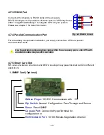
Страница 36: ...tion you simply connect two UPSs via parallel communication cable Use the parallel communication cable within the accessory pack Link UPS with unsuitable cable may result in accident 4 7 5 Smart Card...

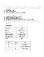
Страница 37: ...t to wakeup PC Send e mail and SNMP trap to notify users Provide InsightPower Client software to protect public operating systems Provide InsightPower Manager to monitor all of the UPS information in...

Страница 38: ...ation practices Configurable UPS shutdown delay time Configurable input signal as shutdown UPS or battery test Has the ability to protect up to 6 computers unattended shutdown gracefully Technical Spe...

Страница 39: ...ult ON SW1 Normal Open Normal Close SW2 Default Settings Customized Settings 3 ModBUS Card Optional Features Translate UPS RS232 protocol into another RS232 and RS422 485 Modbus protocol Device ID is...

Страница 40: ...l time temperature humidity and other environmental condition monitoring Monitors the status of 4 user provide contact devices to protect your critical equipments Technical Spec Temperature Range 0 65...

Страница 41: ...and test UPS Wake On LAN packet to wakeup PC Send e mail and SNMP trap to notify users Provide InsightPower Client software to protect public operating systems Provide InsightPower Manager to monitor...

Страница 42: ...d After initializing process LCD display will show ON AUTO BYPASS In the meantime UPS output is supplied by the bypass source and the LED indicator BYPASS turns on 3 Switch on the Q1 If input power so...

Страница 43: ...3 Switch off Q4 1 Only for maintenance purpose you can turn on manual bypass switch Q3 If you switch on Q3 under normal condition then inverter will turn off and output will be supplied by manual byp...

Страница 44: ...een two UPSs should be less than 5V If it is confirmed then switch on Q4 of both UPSs 5 6 Powering Down Parallel Redundancy If you need to turn off one of the paralleled UPSs 1 press button O of the U...

Страница 45: ...h UPS shows ON AUTO BYPASS 2 Repeat Step1 for another UPS 1 Switch off Q1 of both UPSs 2 Confirm both UPSs are completely shutdown 3 Switch on Q3 of both UPS Reserve power source supplies the loads LC...

Страница 46: ...mber Turn on when UPS is in manual bypass mode 4 Fault Red Turn on when any fault occurs 5 LCD Display LCD screen Multi language Chinese tradition Big5 English 6 ESC page up 7 8 Configuration i and j...

Страница 47: ...ult System FW Power Module FW Date Time Change Password Change Admin User Parallel UPS ID Setting Audible Enable Disable Mute Display Language Serial COM ID Output Setting Inverter Voltage 220 230 240...

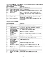
Страница 48: ...event occurs you will see the sign flashes You can press j to see the details For example K O N Q E R F T L O V N I A M N I A M T U P N I K C E H C K O N Q E R F T L O V T U P N I K C E H C N I A M N...

Страница 49: ...ehind UPS are not powered UPS cuts off the output BYPA MAINS LOAD NOT POWERED Maybe due to UPS automatically shutdown by itself Manually switch off the output circuit breaker 2 SOFT START BYPA MAINS O...

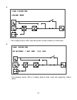
Страница 50: ...y power 4 ON AUTO BYPASS LOAD UNPROTECTED BYPA MAINS ON AUTO BYPASS LOAD UNPROTECTED BYPA MAINS This message means UPS is in bypass mode In the mean time main power source and battery are cut off So t...

Страница 51: ...ONLINE MODE This message means UPS is operating under normal condition normal mode 6 BYPA MAINS LOAD PROTECTED ON BATTERY BAT REM 1123 MIN This message means UPS is in battery backup mode Loads are su...

Страница 52: ...RY BAT REM 2 MIN This message means UPS is in battery backup mode and remaining backup time only 2 minutes left Battery power is nearly exhausted 8 BYPA MAINS LOAD PROTECTED BAT TEST This message mean...

Страница 53: ...source 10 BYPA MAINS LOAD UNPROTECTED ON MANUAL BYPASS This message means UPS is in manual bypass mode When service personnel performs the maintenance work UPS must be transferred into this mode first...

Страница 54: ...r i to select desired item then confirm by press E C N P A U N T E E E R T S U N I A M S P U S A E M E C N P A U N T E E E R T S U N I A M S P U S A E M P MEASURE by j or i to Measure Select this item...

Страница 55: ...3 3 T V V U 0 0 P T 0 0 U 2 2 S 2 2 R O S P U Y C N E U Q E R F z H 0 0 5 V 0 8 3 V 0 0 2 2 T V V 0 0 8 8 3 3 T V V U 0 0 P T 0 0 U 2 2 S 2 2 R O S P U E 0 5 R E T R E V N I E P M E T n E 0 5 C F P R...

Страница 56: ...gure 4 3 2 1 D R O W S S A P N I M D A c d S E Y U O Y E R A E R U S 4 3 2 1 D R O W S S A P N I M D A c d S E Y U O Y E R A E R U S Use j or i to select the first number then press will go to t next...

Страница 57: ...S A P Y B 2 Move cursor by j or i to select voltage range then Press to confirm the choice S E Y c d E E R U S U O Y E R A 2 E 2 G A T L O V S 5 1 V 0 G N A R S A P Y B S E Y c d E E R U S U O Y E R A...

Страница 58: ...c E R U S U O Y E R A S E Y d E D O M E E L C L B I B A M A N E S I D 9 O N O C E c E R U S U O Y E R A S E Y d E D O M E E L C L B I B A M A N E S I D 9 O N O C E c E R U S U O Y E R A S E Y d R E T...

Страница 59: ...lect the desired charging current Press E R U S U O Y E R A S E Y c A 7 T N E R R U C R E G R A H C d E R U S U O Y E R A S E Y c A 7 T N E R R U C R E G R A H C d to confirm the choice Default 7A 4 M...

Страница 60: ...N A H C E M I T E G E T A D E R U S U O Y E R A S E Y d D R O W S S A P N I M D A D R O W S S A P R E S U 2 Move cursor by j or i to change the DATE TIME Press to confirm the choice This item is user...

Страница 61: ...M I S E R U S U O Y E R A d 1 0 D I M O C L A I R E S E R U S U O Y E R A S E Y c d 1 0 D I M O C L A I R E S E R U S U O Y E R A S E Y c d j or i to setup Press to confirm the choice etup the contras...

Страница 62: ...N O S T N U O C 1 2 1 E M I T N O I T A R E P O L A T O T D Y 0 0 3 2 0 Y R E T T A B N O S T N U O C 0 0 1 M H 5 2 0 1 S S A P Y B N O S T N U O C 1 2 1 E M I T N O I T A R E P O L A T O T D Y 0 0 3...

Страница 63: ...E E S A R E E R U S U O Y E R A S E Y c d T S E T Y R E T T A B L A U N A M E G R A H C T S O O B E C R O F T S E T P U T E S L A U N A M E confirmed again T S E T D E L D N A R E Z Z U B T L U S E R...

Страница 64: ...O I S R E V W F N S E M I T M E T S Y S c d Press to execute MANUAL ATTERY TEST B This item is only accessible for a to c a dministra r Password will be nfirmed gain o Press to execu ED TEST te BUZZE...

Страница 65: ...000 InsightPower Manager Shutdown Agent Application Shutdown OSCentralized Management Remote Monitoring InsightPower Client UPSentry Smart 2000 InsightPower Manager Shutdown Agent Support OS Windows L...

Страница 66: ...e Master Slave software structure need not to purchase another SNMP card Unattended operating systems shutdown and files saving Supports Windows hibernation feature Programmable actions FlexAction Rem...

Страница 67: ...n graphical format Such as input output voltage frequency battery volts backup time 2 Power Event Management UPSentry Smart 2000 provides a lot of flexible tools to manage different power events or UP...

Страница 68: ...rd voice message and text the pre record voice Shutdown OS Event Log Popup Message Execute External Command Transmit an audible message 3 Administrator can setup tw will popup when reach the loading l...

Страница 69: ...Monitor programs can c to a Service program 7 5 onnect Programmable actions Batch SNMP configuration Remote and local UPS real time management Generate routine reports Schedule shutdown restart and t...

Страница 70: ...rate historical report and can be transferred into EXCEL file Setup a periodically analyzing report SNMP SNMP SNMP InsightPower Manager Service RS232 485 RS232 485 Network InsightPower Manager Monitor...

Отзывы: