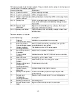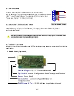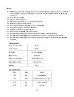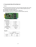
4-10
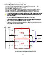
-6-4 Wiring (Parallel Redundancy, dual input)
1. Confirm input and bypass input breaker (Q1 and Q2) is cut off (Refer to Fig. 4-2).
ing suitable cable and lug (Refer to Table 4-3).
4
2. Confirm manual bypass circuit breaker (Q3) is cut off.
3. Confirm output breaker (Q4) is cut off.
4. According to UPS model you select, us
5. Connect all cables to the right terminal or location as indicated (Refer to Fig. 4-1).
6. Connect parallel communication cable between UPS1 and UPS2 (Refer Fig. 4-4).
1. For parallel redundancy installation, the total cable length of input must be equal
to output. This regulation prevent unbalanced loading share between two UPSs
under reserve mode.
i.e. : Res1 + OP1 = Res2 + OP2 (Deviation must be less than 10%)
2. Two UPSs must be the same rating/capacity for parallel installation. Different
rating can’t link to the other and may result in accident.
3. NH series can only parallel link to another one UPS ( 1+1 redundancy ), please
don’t parallel link more than two UPSs.
AC I/P 2
AC I/P 1
Fig. 4-4 Wiring (Parallel Redundancy, dual input)
Res1
Res2
IP1
IP2
O/P
Main I/P
Reserve I/P
Parallel Port
UPS1
O/P
Main I/P
Reserve I/P
Parallel Port
UPS2
Load
Parallel C
ab
le
OP1
OP2

