Button / Screen GCL Programming
Page 82 of 126
eZNT-Wi Programmable Wi-Fi Thermostat Application Guide
Edition 1.4
Each row of touch areas 1-4 and 5-8 can be configured internally as 1, 2, 3 or 4
buttons. This allows for larger areas to be treated as a single button to match the
button overlay used.
The follow table summarizes the options available for a button row.
Buttons per Row
Top Row
Touch Areas 1-4
Bottom Row
Touch Areas 5-8
1 Button
1+2+3+4
5+6+7+8
2 Button
1+2 and 3+4
5+6 and 7+8
3 Button
1 and 2+3 and 4
5 and 6+7 and 8
4 Button
1, 2, 3, 4
5, 6, 7, 8
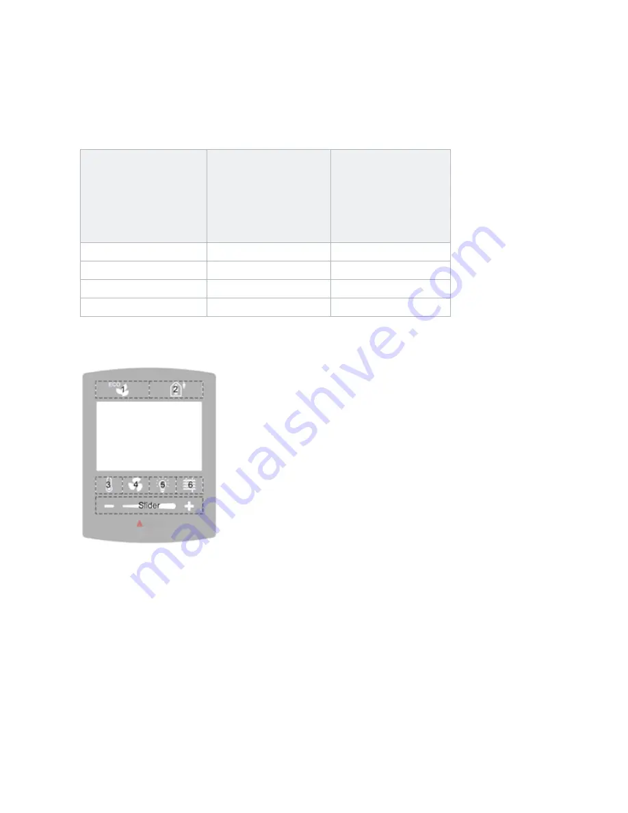
The following figure shows the top row configured as 2 buttons:
Touch areas 1+2 are combined for the ECO button, and touch areas 3+4 are
combined for Occupancy. The Bottom row has the 4 touch areas configured as 4
buttons. Button positions 5 to 8 are each configured to an individual function.
In the previous figure, the slider active zone is located at the bottom of the display
and is always present regardless of what button overlay is used with firmware
before version 3.40R3.1.3. The slider is typically used to adjust light levels or
temperature setpoints in conjunction with a sticky button. The idea is to push a
button such as Temp/Fan/Light/Blind, which through a sticky button arrow indicates
that a specific mode is enabled. The slider is then used to set that mode’s setpoint.


