


C h a p t e r 11 C o n v e n i e n t F u n c t i o n s
11 - 5 1
11.2.2.9
Enabling/Disabling the Online Monitoring Function
In the
Ether Link Configuration
window, users can execute or test the Ether Link constructed by means of the
online monitoring functions provided by NWCONFIG. The users can enable/disable the function of monitoring a
single node/multiple nodes online.
Enabling/Disabling
Description
Single node
Function
Enabling or disabling the function of monitoring the node selected
online
Condition
The users have to make sure that ISPSoft can connect to the PLC
selected normally, and they have completed the communication
setting in NWCONFIG.
Multiple nodes
Function
Enabling or disabling the function of monitoring all the nodes online
Condition
The users have to make sure that all the nodes are connected to a
network, and can connect to ISPSoft through Ethernet. The
connection type that the driver selected in the
Driver Name
drop-down list box in the
Select a Driver
window uses must be
Ethernet.
*. Please refer to section 20.1.3 from ISPSoft User Manual for more information about the communication setting in
NWCONFIG.
Before the users enable the online monitoring function, they have to make sure that all the nodes are
connected according to the network framework created in NWCONFIG, and can operate normally.
(a) Every node has been connected to a network according to the network framework created in NWCONIFG.
(b) The users have set the parameters for Ethernet ports of the nodes by means of HWCOFNIG, and the
parameters have been downloaded to the PLCs and the modules. The setting of the parameters must be
consistent with the setting in NWCONFIG.
(c) The parameters related to an Ether Link have been downloaded to the PLC selected.
(d) Every node is powered up, and can operate normally.
A. Enabling a Monitoring Function
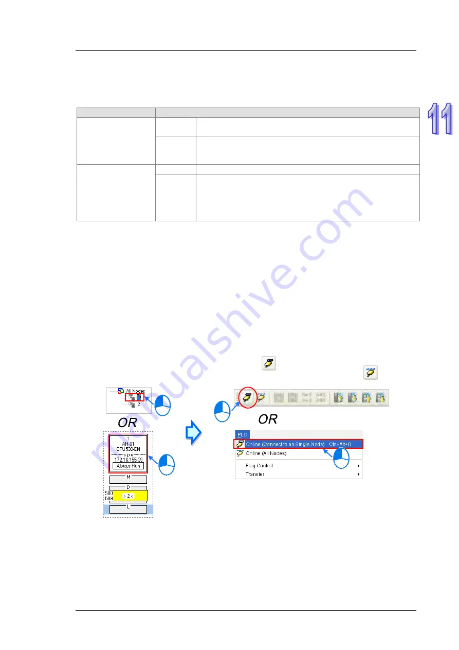
Enabling the function of monitoring a single node
Method 1
Select a data demanding node, and then click
on the toolbar, or
Online (Connect to a
Single node)
on the
PLC
menu. When the data demanding node is monitored,
on the
toolbar is pressed.
Содержание AH500 series
Страница 35: ...AH500 Hardware and Operation Manual 2 2 2 12 2 Profiles 2 117 2 12 3 Dimensions 2 118 ...
Страница 153: ...AH500 Hardware and Operation Manual 2 120 MEMO ...
Страница 167: ...AH500 Hardware and Operation Manual 3 14 MEMO ...
Страница 183: ...AH500 Hardware and Operation Manual 4 16 2 Pull up the clip Type I Type II 3 Remove the terminal block Type I Type II ...
Страница 343: ...AH500 Hardware and Operation Manual 6 38 MEMO ...
Страница 361: ...AH500 Hardware and Operation Manual 7 18 MEMO ...
Страница 403: ...Chapter 8 Hardware Configuration 8 42 MEMO ...
Страница 412: ...Chapter 9 Network Configuration 9 9 ...
Страница 445: ...AH500 Hardware and Operation Manual 9 42 MEMO ...
Страница 552: ...Chapter 12 Troubleshooting 12 3 12 1 3 Troubleshooting Procedure ...
Страница 649: ...AH500 Hardware and Operation Manual A 8 ...
Страница 657: ...AH500 Hardware and Operation Manual A 16 MEMO ...
Страница 658: ...B 1 Appendix B Device Addresses Table of Contents B 1 Device Addresses B 2 ...
Страница 663: ...AH500 Hardware and Operation Manual C 4 MEMO ...
Страница 681: ...AH500 Hardware and Operation Manual 3 14 MEMO ...