background image


Installation

Installation Manual

8

Foundation

The PCS cabinet is recommended to be mounted on concrete floor. Follow the illustration below to 
prepare the groundwork.

Before installing a PCS cabinet, it is recommended to have a solid foundation established. The 
following information is provided to serve as a guide for the setup of a recommended foundation.

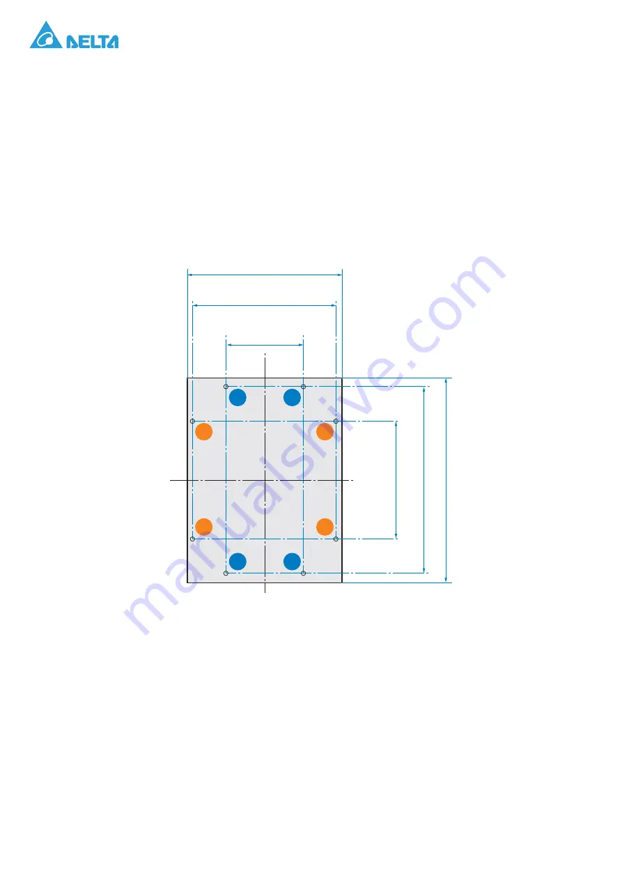
The footprint boundary area of the PCS is 600 x 800 mm (23.62 x 31.49 in.), and there are two ways for 
mounting:

1. Mounting by the left and right sides of the unit base: Drill four holes for M16 expansion bolts at 

the 4 corners of an area of 560 x 460 mm (22.05 x 18.11 in.) as marked in number 1.

2. Mounting by the front and rear sides of the unit base: Drill four holes for M16 expansion bolts at 

the 4 corners of an area of 300 x 726 mm (11.81 x 28.58 in.) as marked in number 2.

Figure 4.

Mounting Layout and Anchoring Holes Placement Variations (Top View)

Once the anchoring holes are completed, insert the expansion sleeves into the anchoring holes:

Remove four M16 expansion bolts from the accessory kit.

Separate the nuts and washers from the bolts.

Once the expansion sleeves are individually separated, insert each one into the anchoring 
holes.

560 mm (22.04 in)

Expansion bolt

600 mm (23.6 in)

Cabinet outline dimension

800 mm (31.5 in)

Cabinet outline dimension

300 +5 mm (11.8 in)

Expansion bolt

-

726 mm (28.6 in)

Expansion bolt

460 

+

5 mm (18.1

1

 in)

Expansion bolt

-

1

1

1

1

2

2

2

2

Содержание 100kW PCS

Страница 1: ...100kW Power Conditioning System PCS Installation Manual Version 1 0 0...

Страница 2: ...ns 3 Typographical Conventions 4 Introduction 5 Overview 5 Features 6 Applications 6 Accessory Kits 6 Installation 7 Before You Begin 7 Unpacking the Unit 12 Installing the PCS Onsite 15 Securing a Ca...

Страница 3: ...Installation Manual ii Warranty 60 Appendix 61 Specifications 61 Glossary 63 Screw Torque Table 65...

Страница 4: ...r usage to the Manual is prohibited without obtaining Delta s prior written permission As the product will be developed and improved continuously Delta may modify or update the Manual from time to tim...

Страница 5: ...About this Manual Installation Manual 1 About this Manual Version Control Table 1 Version Control Rev Change Description Date 1 0 0...

Страница 6: ...ard procedure of installing the PCS and information about configuration of the unit It does not provide details of batteries Audience The manual is intended for anyone who needs to install Delta 100kW...

Страница 7: ...tion or commissioning of the PCS read through the entire manual and note all DANGER WARNING CAUTION and NOTICE Statements All electrical installations must comply and be in accordance with all the sta...

Страница 8: ...rsonnel In operation the PCS wiring and connections can have hazardous high voltages and currents present thus only authorized and qualified personnel shall install and or maintain the PCS In some ope...

Страница 9: ...peak shaving enables load shifting for time of use savings and provides real power and reactive power compensation to improve power quality With Delta s PCS solution you can realize the fullest value...

Страница 10: ...agement Power Dispatch Load shifting for Time of Use saving Power quality improvement P Q Control Frequency Regulation Emergency backup power Accessory Kits Check that the following items are included...

Страница 11: ...nstructions An equipment grounding conductor or a grounded metal and permanent wiring system is required for the PCS connection This should be run with circuit conductors and connected to the equipmen...

Страница 12: ...2 05 x 18 11 in as marked in number 1 2 Mounting by the front and rear sides of the unit base Drill four holes for M16 expansion bolts at the 4 corners of an area of 300 x 726 mm 11 81 x 28 58 in as m...

Страница 13: ...ired The PCS is forced air cooled The cabinet is separated into two compartments front and rear compartments In the case of front compartment a heat exchanger is mounted on the front door and air is d...

Страница 14: ...ise levels The PCS should not be installed in an area that is excessively dusty as this may decrease the performance of the air cooling system The PCS must not be installed in areas in which dust cont...

Страница 15: ...ntenance from rear side as shown in Figure 7 Figure 7 Front and Rear Maintenance Clearance Distance When installing the PCS take into consideration the necessary ventilation space as well as the space...

Страница 16: ...top cover 3 Remove the top cover Figure 9 Removing a Top Cover WARNING The 100kW PCS and crate have a combined weight of approximately 418 kg 921 lbs DO NOT attempt to lift and or move the package uni...

Страница 17: ...Remove the screws securing the left and right sidewalls from the shipping package 5 Remove the right and left sidewalls Figure 10 Removing Left and Right Sidewalls ON OFF STANDB Y RUN FAULT ON AC DIS...

Страница 18: ...Remove the front and rear walls Figure 11 Removing Front and Rear Walls Upon unpacking the page inspect the unit for signs of damages that may have been caused during shipping If damage is found immed...

Страница 19: ...llation site should be restricted to qualified service personnel Battery Ground Fault Concerns The following are concerns surrounding potential risks of DC ground faults and the possible causes The pr...

Страница 20: ...to a lack of knowledge on the part of a rigger To prevent hoisting and rigging hazards it is necessary for the operator to understand the following the weight of the load and rigging hardware the cap...

Страница 21: ...om a Pallet CAUTION TO MOVE THE 100KW PCS USE LIFTING EQUIPMENT THAT HAS APPROPRIATELY RATED LIFT CAPACITY CAUTION IF USING LIFTING LUGS BE SURE THE SPREADER BAR IS SUFFICIENTLY LONG TO PREVENT DAMAGE...

Страница 22: ...open Figure 13 Opening a Front Panel Make sure the door limiter at the bottom of the panel engages in the track to keep the front panel from closing accidentally Figure 14 Engaging the Front Panel Li...

Страница 23: ...anel Figure 15 Opening a Rear Panel Make sure the door limiter at the bottom of the panel engages in the track to keep the rear panel from closing accidentally Figure 16 Locking a Rear Panel in a Cabi...

Страница 24: ...rews from the front and rear sides 7 At least two individuals are required to safely lift the top cover Lift both ends simultaneously and remove the top cover from the PCS Place the cover in a clean w...

Страница 25: ...nel Make sure the front panel closes correctly with the cabinet The top and bottom of the panel are flush with the cabinet if the panel is closed correctly 11 Rotate the door handle to the locked posi...

Страница 26: ...Installation Installation Manual 22 12 Repeat for the rear panel Figure 20 Closing a Rear Panel...

Страница 27: ...REQUIRED WEIGHT CAUTION THE UNIT SHOULD NOT BE INSTALLED WITH THE CABINET DOORS OPEN WARNING Before proceeding with the normal operation of the hoist the operator s must be trained accordance with th...

Страница 28: ...installation site secure the PCS to the site as described in Securing a Cabinet in a Final Location on page 30 18 Remove the hoist 19 Once the cabinet is secured to the location install the top cover...

Страница 29: ...Pallet CAUTION TO MOVE THE 100KW PCS USE A FORKLIFT THAT HAS AN APPROPRIATELY RATED LIFT CAPACITY AND A 915 CM 36 INCH FORK SPAN CAUTION THE ENCLOSURE MUST BE LIFTED FROM THE BOTTOM THE ENCLOSURE MUST...

Страница 30: ...rs c Remove the base covers Place them in a clean work surface for later use The covers must be replaced after cabinet installation and cable routing is completed Figure 24 Removing Left and Right Bas...

Страница 31: ...aligned insert the forks into the channels until they are completely through the opposite side of the insertion channels f Carefully lift the cabinet Figure 25 Lateral Handling of PCS WARNING Take car...

Страница 32: ...sing a PCS from a Pallet b Remove the screws securing the front rear base covers c Remove the front and rear side panels Figure 27 Removing Front Rear Base Covers ON OFF STAND BY RUN FAULT ON AC DIS C...

Страница 33: ...pletely through the opposite side of the insertion channels f Carefully lift the cabinet Figure 28 Front rear Side Handling 3 Once the cabinet is secured to the location install the top cover see Secu...

Страница 34: ...unlock the front panel b Rotate the door handle to open the front panel and pull the door open Figure 29 Opening a Front Panel Make sure the door limiter at the bottom of the panel engages in the trac...

Страница 35: ...nded c Repeat for the rear panel Figure 31 Opening a Rear Panel Make sure the door limiter at the bottom of the panel engages in the track to keep the rear panel from closing accidentally Figure 32 Lo...

Страница 36: ...Installation Installation Manual 32 d Install the top cover and secure the top cover to the 100kW PCS with screws Figure 33 Installing the Top Cover...

Страница 37: ...ottom of the cabinet are engaged with the front panel g Rotate the door handle to lock Figure 34 Closing a Front Panel Note Make sure there is no gap between the front panel and the cabinet An imprope...

Страница 38: ...Installation Installation Manual 34 3 Repeat for the rear panel Figure 35 Closing a Rear Panel...

Страница 39: ...nserted in their respective anchoring bolts 6 Repeat for the remaining anchoring bolts 7 Once all nuts are inserted tighten the anchoring bolts in an ascending order See the following figure Figure 36...

Страница 40: ...ttery fault 3 Risk to system reliability due to ground fault Shock Hazard Ensure that no DC voltage is being supplied to the PCS and that no AC voltage is present on the AC wiring Failure to do so cou...

Страница 41: ...issues such as cracks by stress or holes by penetration in the container create an opportunity for electrolyte to seep out of the container and contact the battery To prevent possible ground fault ri...

Страница 42: ...n to OFF state OFF Horizontal turn clockwise to vertical position to ON state Figure 37 PCS Front View with AC DC Disconnects Status ON OFF STANDBY RUN FAULT ON AC DISCONNECT OFF ON DC DISCONNECT OFF...

Страница 43: ...o the OFF horizontal position wait at least five minutes before opening the front door 1 Rotate the switch handles to the OFF position to disconnect the AC and DC disconnects Figure 38 Disconnecting t...

Страница 44: ...d swing it open until it locks in place Figure 40 Opening a Front Panel Make sure the door limiter at the bottom of the panel engages in the track to keep the front panel from closing accidentally Fig...

Страница 45: ...s used the wiring must comply with the local regulations Table 2 AC Wire Sizing and Ratings Cable Type Solid Copper Conductor Voltage Rating 600 Volts or greater Temperature 70 C or greater Gauge 53 4...

Страница 46: ...closed in the accessory kit 2 x 6 pin green connector enclosed in the accessory kit 1 x 2 pin green connector enclosed in the accessory kit 1 x 3 pin green connector enclosed in the accessory kit 3 x...

Страница 47: ...hes the wire inspection indicator as shown in the following figure Figure 42 Inserting a Power Cable into a Cable Lug Depth Reference Diagram 3 For safety purpose use heat shrinkable tubing on the jun...

Страница 48: ...of the unit base and through the wire glands in front of the DC cable glands Plug these connectors into the relevant connector bases built in at the inner side wall of the cabinet adjacent to the DC t...

Страница 49: ...m Pin Assignment Notes CNJ3 1 Digital Output 1 1 Dry Contact 1 only for internal use Max 24Vdc 10mA 2 Digital Output 1 2 3 Digital Output 2 1 Dry Contact 2 Max 24Vdc 10mA 4 Digital Output 2 2 5 Digita...

Страница 50: ...m the accessory kit For CANbus connect two prepared 1 32 mm2 wires to pins 5 and 6 Figure 46 CNJ13 Pin Assignment Table 7 CNJ13 Pin Assignment Item Pin Assignment Notes CNJ13 1 RS485 B3 For BMS 2 RS48...

Страница 51: ...6 wires connected to pins 1 to 6 on the 6 pin connector from the accessory kit as shown in Figure 47 and Table 8 Figure 47 CNJ1 Pin Assignment Table 8 CNJ1 Pin Assignment Item Pin Assignment Notes CNJ...

Страница 52: ...er 2 RS485 B2 3 NC 5 CAN H2 For PCS parallel 6 CAN L2 7 CAN H3 For voltage detection 8 CAN L3 Table 10 Used for Upper Controller Use 3 pin Item Pin Assignment Notes CNJ7 1 RS485A2 The same RS485 termi...

Страница 53: ...the black start Demand Response Management RJ45 Demand Response Management The inverter provides a RJ45 port to support the connection to a demand response enabling device DRED The support is require...

Страница 54: ...the following figure Figure 49 X1 RJ45 Socket Location for DRED Interfacing DRM7 The export power to the grid is no more than 75 of the rated power DRM8 The export power to the grid is 100 of the rate...

Страница 55: ...n example As for the other cases please remove the relevant side cover of the unit base to lead the cables and wires into the cabinet To do the wiring works from the front bottom side of the PCS first...

Страница 56: ...DC L1 L2 and L3 along with the protective covers and relevant terminals are illustrated See the following figure Figure 52 DC and AC Connection Labels and Terminals Note There are 3 sets of Positive a...

Страница 57: ...nd use heat shrinkable tubing on the junction between the cables and lugs to prevent the exposure of the conductive part 2 Remove protective cover of DC terminals Remove the protective cover in front...

Страница 58: ...terminals then lead the DC cables with two hole lugs through the DC cable glands into the PCS Connect and secure these cables to the relevant DC and DC terminals Figure 55 Positive and Negative DC Ca...

Страница 59: ...ole lugs in the accessory kit and use thermal casing to prevent the exposure of the naked part 2 Remove protective cover of AC terminals Remove the protective cover in front of the AC terminals as the...

Страница 60: ...s by Allen wrench then lead the AC cables with two hole lugs through the AC cable glands into the PCS connect and secure these cables to the relevant L1 L2 and L3 terminals Figure 59 AC Cable Connecti...

Страница 61: ...copper plate at the inner side wall of the cabinet adjacent to the AC terminals as shown below Figure 61 Grounding Cable Connection with Grounding Copper Bar Note The grounding cable only needs a 53...

Страница 62: ...the 1 0 600V wire 2 Remove the nuts securing the plexiglass cover then remove the plexiglass cover Figure 62 Removing the Plexiglass Cover 3 Remove the two hole terminal on the copper bar and crimp t...

Страница 63: ...on When PCS100 is configured in IT system application N wire is forbidden to connected to PCS100 Besides the Isolation Monitor Device IMD is essential Customer must install IMD in proper location in t...

Страница 64: ...t within the reasonable control of the operation design 4 repaired modified moved or installed by any party without Delta s prior written authorization 5 damage due to accidents such as fire inundatio...

Страница 65: ...mpliant Power Factor 1 to 1 continuously adjustable Charging discharging Transfer Time 100 ms 90 rated power Power Response Time 40 ms 0 100 rated power Battery Input Performance DC Voltage Range 750...

Страница 66: ...put relays User Interface 4 9 inch LCD screen with push button Fault LEDs Emergency Stop Local EPO button remote control Communication RS 485 Modbus RTU CAN System Characteristic Peak Efficiency 97 2...

Страница 67: ...mergency power off ESS Energy storage system Galvanic isolation No conductive connection between two component parts GEC Grounding Electrode Conductor GET Grounding Electrode Terminal IEEE The Institu...

Страница 68: ...ded Power dissipation is released mainly as heat PVC Polyvinyl chloride RJ 45 Abbreviation for standardized eight pole electrical connector connection RJ stands for Registered Jack standardized socket...

Страница 69: ...red Steel Plate Steel Plate 0 8 0 15 1 4 0 2 2 0 0 2 Steel Plate Aluminum Plate 0 7 0 1 1 0 0 15 1 6 0 2 Aluminum Plate Aluminum Plate Plastic Aluminum Plate 0 6 0 1 0 8 0 15 1 2 0 2 Plastic Steel Pla...

Отзывы: