16
Installation and Operating Manual
IP227, Rev DA
Mobrey MCU200 Series
February 2020
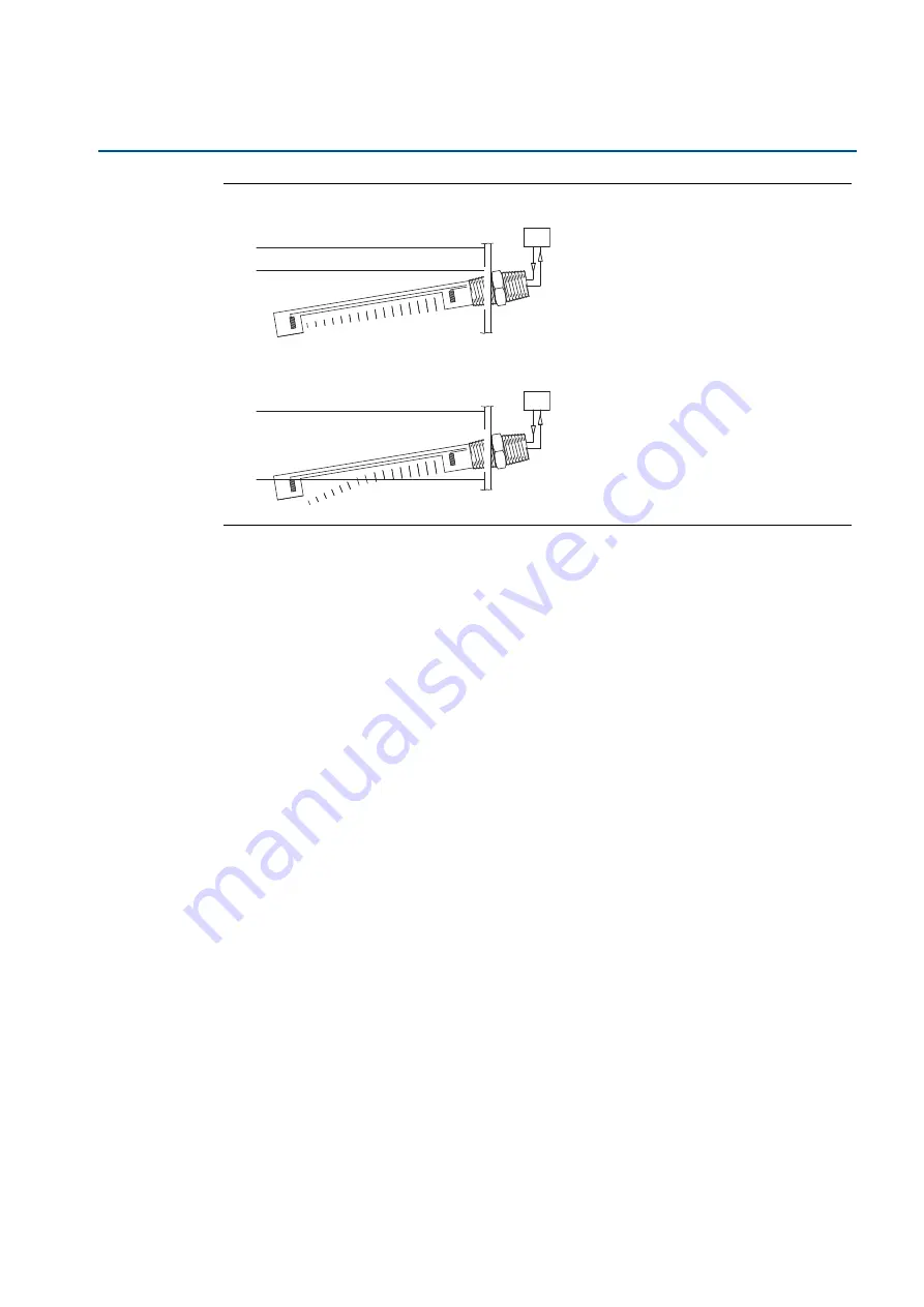
Figure 10. Interface detector by reflection method
5.
Maintenance
Safety maintenance: This is limited to periodic inspection by a qualified person to ensure that
the installation including wiring and equipment housing is safe.
6.
Fault finding
At least one LED should always be illuminated.
– If none are illuminated, check the power supply to the control unit.
If the Fault LED is illuminated while the sensor is connected, check the coaxial cable to the
sensor for incorrect wiring or damage.
– Particularly check the continuity of extension cables, connection of crimped connectors
on cable ends.
– For other types of sensor, change the cable check switch to the “OUT” position
(see
“Internal switch settings” on page 9
). The PCB can be then checked by linking the
two terminals (both labelled as “E”) on the sensor terminals. This should stop the Fault
LED illuminating.
If the sensor is giving incorrect indications, check the gain (see
“Applications” on page 11
).
– For a gap sensor giving a false dry indication, this could be due to aeration or solids in the
liquid.This problem can be overcome by increasing the gain, slightly, to a maximum of
X-2. This increases the sensitivity and is appropriate for high level alarms.
– For a gap sensor giving false indication, this could be due to cross-talk between cables.
Check that all junctions use coaxial connectors with the outer casings isolated.
Separate the two coaxial cables for long cable runs. A ‘false wet’ indication can also be
caused by viscous liquids clinging to the sensor: sensitivity can be decreased slightly by
reducing the gain to X-6 minimum and then checking for reliable operation in the liquid.
Air
Oil
Air
Oil
Water
Water
MCU200
Series
Controller
MCU200
Series
Controller


