background image

LINKnet I/O Tab 

Page 35 of 67 

eZV-440 Version 2.1 Application Guide 


Document Edition 2.5 


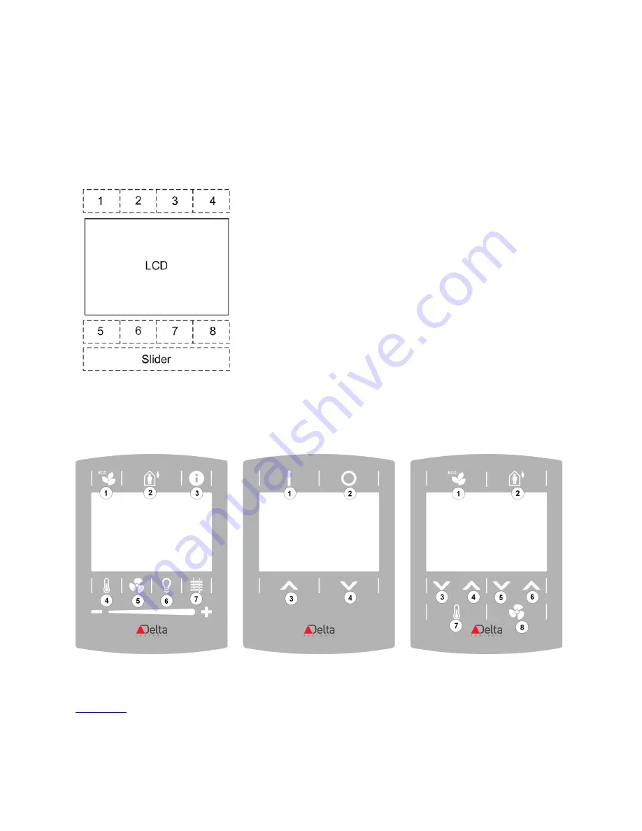
To assign functions to the button and slider elements on the eZNS: 

Using the configuration graphic, you can assign specific functions to every button and slider 
element. There are as many as 95 button overlay combinations available for the eZNS network 
sensor. Fortunately, all these combinations are based on this single layout which consists of 8 
buttons and the slider element:  


Not all the buttons are used in every button overlay. In some cases, the slider element can be 
converted into 2 additional up and down buttons, or omitted. In overlays where there are less 
than 8 buttons, button areas are merged together and counted as one (see the examples below). 


For more information about the button overlays, see the 

Button Overlay Selection Summary


document

 on the Delta Controls support web site support.deltacontrols.com. 

Содержание eZV-440

Страница 1: ...eZV 440 Application Guide Edition 2 5 ...

Страница 2: ...rs of Delta Controls Inc products Delta Partners may print PDF documents for their own internal use or for use by their customers Authorized Delta Partners may engage a printing or copying company to produce copies of released PDF documents with the prior written permission of Delta Controls Inc Information in this document is subject to change without notice and does not represent a commitment to...

Страница 3: ...ration Graphic 7 Selecting Between Multiple Controllers 7 Save to Flash Save to PC and Load from PC 7 Shortcuts 8 Configurable and Programmable eZV Controllers 9 LINKnet Devices 9 Data Exchange 9 Alarming 10 Trend Logs 11 Programming 12 Commissioning 15 VAV Balancing Tasks 15 1 Enable Balancing Mode 15 2 Set the VAV Box Size 15 3 Set Manual Balancing Dampers 16 4 Set the Airflow Setpoints 16 5 Che...

Страница 4: ... Up Damper Feedback 25 Set Up Other Supporting Inputs 25 Set Up an Airflow Sensor 26 Local Outputs Tab 27 Additional Configuration Graphic Fields in Programmable Controller 28 Set Up an Output 28 Set Up Actuator Damper Output 31 LINKnet I O Tab 32 Device Information 32 Set Up a eZNS Network Sensor 33 Set Up a DNS 24L Network Sensor 39 Setpoints Tab 42 Space Temperature Setpoints 42 Discharge Air T...

Страница 5: ...4 Fan Operation 55 Single Speed Parallel Fan Sequence 55 Modulating Speed Parallel Fan Sequence 56 Single Speed Series Fan Sequence 56 Modulating Speed Series Fan Sequence 57 Appendix A Database Configuration Objects 58 Input Configuration Objects 58 Occupancy Configuration Objects 59 Output Configuration Objects 60 Setpoint Configuration Objects 61 Device Instance BACnet Address Object 62 Appendi...

Страница 6: ...ontrol Language GCL programming About This Guide This application guide introduces the controller and describes the differences between the configurable and programmable models The guide also explains how to use the configuration graphic in ORCAview 3 40 R3 and higher to set up your eZV 440 controller The product name eZV 440 in this guide refers to both the configurable and programmable models un...

Страница 7: ...an download the configuration graphic from the eZV 440 product web page on the Delta Controls Support web site support deltacontrols com and install it on your operator workstation The version referenced in this guide is B 169041 1 Installing the Configuration Graphic To install the configuration graphic 1 On your operator workstation go to the graphic folder C Users Public Delta Controls 3 40 Sit...

Страница 8: ...ing the configuration graphic the DEV object dialog opens 2 On the Configuration tab click and browse to the graphics folder and select the Main gpc file for eZV 440 controller Click OK 3 In the left window of the ORCAview navigator right click on the eZV 440 controller again Click Open Because you have set it up in step 2 the configuration graphic window should open and will open this way each ti...

Страница 9: ...ation graphic individually for each controller in the ORCAview navigator you can switch between controllers within the configuration graphic When you switch between controllers any changes made in a previous session will be saved automatically before you switch to the next controller To select between multiple controllers In the numerical field at the top of the window enter the BACnet address of ...

Страница 10: ...tcuts There is a quick way to open the ORCAview object dialogs by right clicking on the configured input and output numbers in the configuration graphic In the example below when you right click on the number 1 and select Open SpaceTemp_AI1 the AI1 object dialog opens onscreen ...

Страница 11: ...table below You cannot exceed this number by creating any new objects Controller Version LINKnet objects LNK Event Objects EV Trend Logs TL Programs PG Configurable 1 0 4 0 Programmable 4 5 8 3 For a complete list of eZONE supported object types and number of instances allowed for each object go to the eZONE overview page on the Delta Controls Support web site LINKnet Devices Configurable controll...

Страница 12: ...lists the number of DER and DEL requests that are in use The eZV 440 controller supports Bulk Data Exchange BDE but is limited to 2 BDE objects Each BDE object can hold up to 12 tag and object entries on the object s Transmit Entries tab For more information about Data Exchange types go to the Delta Controls Technical Support web site knowledge base article KBA 1813 Alarming The programmable contr...

Страница 13: ...o 4 which are pre configured in the default database to monitor specific heating and cooling objects However all TLs can be modified to monitor other objects you can change the method of data collection Change of Value or polling as well as the polling interval However fields that display the maximum and total sample size are read only It is not recommended to use Change of Value for objects that ...

Страница 14: ... unsupported GCL functions and statements for the eZVP 440 programmable controllers is recorded in KBA 2137 on the Technical support web site The ORCAview and enteliWEB GCL editors are not aware of these limitations so using an unsupported function in an eZVP 440 controller will not register a syntax error in these GCL editors Overwriting the Algorithm You can overwrite the algorithm by programmin...

Страница 15: ...enough duct air for heating and cooling BV800 AirflowStatus Flow Loop Manager Controls airflow through the damper AV831 DamperDemand Heat Stage Manager Controls heating sequences of operations AV808 AirflowDemand AV803 Heat1 AV804 Heat2 AV805 Heat3 AV810 Fan1 Occupancy Manager Determines the occupancy mode in the space at any time MV800 OccupancyMode Temperature Setpoint Manager Controls the activ...

Страница 16: ...ox Mode Manager Demand Control Ventilation MV800 Occupancy Mode AV800 CurrentHeating Setpoint AV801 CurrentCooling Setpoint AV802 HeatCool Load AV830 Air Flow Setpoint AV831 Damper Demand VVT AV832 DamperCmd AV808 Air Flow Demand AV803 Heat1 AV804 Heat2 AV805 Heat3 BV800 Air Flow Status Hydronic and Electric Duct MV801 VAVDuct1BoxMode Point s in each algorithm manager box can be used to override t...

Страница 17: ...ate other than None_ When a state other than None_ is selected the object OccupancyMode_ MV800 is automatically assigned a Balancing_ state 2 Set the VAV Box Size In the VAVBoxSize field select the VAV box size you re working with Based on the VAV box size you select the algorithm then enters preset values in the following fields on the AirBalancing tab FlowFactor CoolingMinimum minimum cooling ai...

Страница 18: ...associated VAV AHU is turned off If you are still detecting some airflow then the airflow sensor needs to be zero calibrated For more information about how to zero calibrate the airflow sensor see the section below To auto zero calibrate the airflow sensor Note For best results the AHU fan should be turned off when zeroing the airflow sensor 1 Click the Zero Calibrate button 2 Check the status of ...

Страница 19: ...irflow again to confirm that the airflow is now reading correctly 7 Exit Balancing Mode Exit balancing mode by selecting None_ in the Balancing Mode field Balancing mode also automatically expires after a timeout period that you set in the AV142 object This prevents the system from being stuck in balancing mode if you forget to exit balancing mode after balancing is complete Check Duct Heater Airf...

Страница 20: ...d name Description Name Displays the name of the Device Object This name is also displayed in the ORCAview navigator You can change this name but you are limited to 36 characters Model Number Displays the controller s Delta Controls model number This is a read only field Firmware Version Displays the controller s firmware version This is a read only field Firmware Build Displays the controller s f...

Страница 21: ...r Derived Network Addressing a system of organizing and configuring controllers in a network When DNA is enabled addresses are automatically assigned to a device based on the BACnet network type and the Delta Controls product type so that a device can work out of the box without much set up For more information about DNA see Appendix C of the ORCAview Technical Reference Manual 3 40R1 on the Delta...

Страница 22: ...nfigured If you change from one application type to another the settings of the previous application will be deleted You can save your controller database before switching application types Temperature Units Displays the temperature units used by the eZV 440 controller Select between Celsius and Fahrenheit Airflow Units Displays the airflow units used by the eZV 440 controller Select between CFM l...

Страница 23: ...red occupancy input Hardwired CO2 sensor Damper feedback Airflow sensor Fan status analog MUX binary MUX and window contact Input 6 in the graphic is reserved for the eZV 440 onboard differential pressure sensor Input 5 is typically used for a 0 10VDC damper position feedback when a feedback enabled actuator is present Set Up a Hardwired Temperature Sensor Occupancy overrides can share the same in...

Страница 24: ...lly closed contact wired in series with the temperature sensor SpcTemp OccToggleButton_ Space temperature sensor and the occupancy toggle pushbutton are wired into the same input This can be a normally open contact wired in parallel or a normally closed contact wired in series with the temperature sensor When setting up a temperature sensor majority of the cases would require you to select Temp_10...

Страница 25: ...older manual switch or mechanical time clock input OccOvrdButton_ Network sensor button as an occupancy override button When pushed during unoccupied mode it starts an occupancy override timer When an override has been activated pushing the button will extend the override time by resetting the timer back to its max value During scheduled occupancy periods you cannot switch occupied to standby mode...

Страница 26: ...In the PushButtonOvrdTime field enter how long the button override should last With the OccToggleButton option it is recommended to display the occupancy status as the current occupancy status allows the user to determine if a button press will start an override or cancel an active override This can be done using the OccIndicator_ output option for hardwired occupancy buttons or on the LCD display...

Страница 27: ...orithm will use this feedback signal rather than a calculated damper position based on runtime 3 In the Action Scale Range field select the input scale range that matches your damper feedback signal If you do not select a scale range the default scale range is assumed to be zero to full scale 0 to 100 Set Up Other Supporting Inputs This topic describes how to set up supporting inputs like fan stat...

Страница 28: ...he SpaceTempSetpoint_ option to set up a resistive slider click the sign at the end of the row In the SetpointSliderMinResistance field enter the minimum resistance of the setpoint slider In the SetpointSliderMaxResistance field enter the maximum resistance of the setpoint slider To enter the occupancy setpoint offset range for this resistive slider go to the Setpoints tab and enter the offset in ...

Страница 29: ...Outputs tab in this configuration graphic The Universal Outputs are reconfigured as these outputs depending on the object being controlled Analog 0 10VDC output 5mA maximum 24 VAC TRIAC output 0 5 A maximum The output options for the eZV 440 configurable model are listed here Electric Duct Exhaust Fan Electric Baseboard Occupancy Indicator Hydronic Duct GCL controlled AO Hydronic Baseboard GCL con...

Страница 30: ...Damper Output on page 31 For more information about sequence of operations for the algorithm see page 47 To set up an output 1 In the Function field select the option that applies to your setup every additional heat fan stage should have its own output line Function Select this option if you are Output Stage ElectricBaseboard_ Setting up a baseboard heater Select the equipment s heat stage in the ...

Страница 31: ...on the option that was selected in the Function field and the physical output used to connect to the output device For more information about control types see Appendix B Control Types on page 63 ECM fans may require both an analog speed and a binary stop start signal For example for a modulating series fan sequence that has both an analog speed and binary stop start signal this is how you should ...

Страница 32: ...ge number For ductal heat outputs with multi speed fans 1 is the default value With ECM fans FanMinSpeed see the section below is the default value 0 is the default value for non ductal outputs When you modify these values the fan speed associated with that output is changed For example if you enter 3 in Heat2FanMin the fan will respond to the heating demand at Heat 2 stage by increasing to fan sp...

Страница 33: ...of control used on the damper signal For more information about control types see Appendix B Control Types on page 63 4 If you are using an analog actuator in the Action field choose between direct or reverse control For tri state actuators use the Control Type field to set the damper s open and close direction 5 Click the sign and in OP5 6Runtime enter the amount of time it takes to move the damp...

Страница 34: ... type of network sensor that is connected to it and displays only the fields in the configuration graphic that are relevant to that network sensor Device Information If no LINKnet device is connected to the controller you can select a network sensor device from the drop down list in the Model field This allows you to program offline When a DNS 24L or eZNS network sensor is physically connected to ...

Страница 35: ...he built in temperature sensor on eZNS network sensor is not used SpaceTempControl The built in temperature sensor is used to control the space temperature An input object AI1001 is created the sensor value which will be used by the algorithm to control space temperature MonitoringOnly Input object AI1001 created but its value will not be used by the internal algorithm for space temperature contro...

Страница 36: ...e CO2 demand ventilation setpoint value To set up an occupancy sensor 1 In the Sensor Options section next to OccMotion sensor type select the Function option that is most appropriate for your needs Function Select this option if None The occupancy sensor on the eZNS network sensor is not used OccupancyDetection The motion sensor on the eZNS network sensor is used to detect occupancy MonitoringOnl...

Страница 37: ...tunately all these combinations are based on this single layout which consists of 8 buttons and the slider element Not all the buttons are used in every button overlay In some cases the slider element can be converted into 2 additional up and down buttons or omitted In overlays where there are less than 8 buttons button areas are merged together and counted as one see the examples below For more i...

Страница 38: ... click the sign next to this option in the PushButtonOvrdTime field you can enter how long the button override should last OccupancyOn_ Turn on the occupied mode If you click the sign next to this option in the PushButtonOvrdTime field you can enter how long the button override should last OccupancyToggle_ Toggle between standby and occupied modes during scheduled occupancy periods When pushed dur...

Страница 39: ...ough fan stages after FanCycle is pressed With analog fans fan speed will change by this amount FanMaxSpeed FanMinSpeed 6 FanUp_ Increase the displayed fan speed or toggle through fan stages after FanCycle is pressed With analog fans fan speed will change by this amount FanMaxSpeed FanMinSpeed 6 FanCycle_ Set up the button to display the current fan stage When the up and down buttons are not avail...

Страница 40: ...sabled neither icon is displayed SunMoon_ Sun or Moon icon to be displayed These icons can be used to show day and night occupancy modes 2 Next to Display Setpoints select how the setpoint of the current heating or cooling stage is displayed on the LCD screen Display Option Select this option if you are setting up On Button Press The setpoint is displayed when the Temp Select Temp Up or Temp Down ...

Страница 41: ...only connect to 1 LINKnet device at a time This LINKnet device has to have a device address of 1 in order for it to work with the controller algorithm Multiple LINKnet devices up to 4 are only supported by the programmable controllers To set up the temperature sensor See the temperature sensor set up section under the eZNS on page 33 To set up the humidity sensor See the humidity sensor set up sec...

Страница 42: ...utton override should last OccupancyOn_ Button 2 Turn on the occupied mode If you click the sign next to this option in the PushButtonOvrdTime field you can enter how long the button override should last OccupancyToggle_ Button 1 DNS Fan model Toggle between standby and occupied modes during scheduled occupancy periods When pushed during unoccupied mode it starts an occupancy override timer When a...

Страница 43: ...Button 3 DNS Fan model Decrease the displayed fan speed or toggle through fan stages after FanCycle is pressed With analog fans fan speed will change by this amount FanMaxSpeed FanMinSpeed 4 FanUp_ Button 4 DNS Fan model Increase the displayed fan speed or toggle through fan stages after FanCycle is pressed With analog fans fan speed will change by this amount FanMaxSpeed FanMinSpeed 4 FanCycle_ N...

Страница 44: ... tab Space Temperature Setpoints Name of field Description OccHeatingSetpoint Occupied Heating Setpoint When the controller is in occupied mode heating is turned on when the space temperature drops below this setpoint UnOccHeatingSetpoint Unoccupied Heating Setpoint When the controller is in unoccupied mode heating is turned on when the space temperature drops below this setpoint OccCoolingSetpoin...

Страница 45: ... 0 from the cooling setpoint Discharge Air Temperature Limiting Setpoints These setpoint fields are only enabled if you had configured a discharge air temperature sensor on the Local Inputs tab Name of field Description DATHiLimitSetpoint Discharge Air Temperature High Limit Setpoint The maximum setpoint value set for the discharge air temperature DATLowLimitSetpoint Discharge Air Temperature Low ...

Страница 46: ...Minimum The minimum heating airflow setpoint HeatingMaximum The maximum heating airflow setpoint StandbyMinimum The minimum airflow at Standby mode Setpoint Range Limiting The user setpoints are range limited as follows Setpoint Minimum Value C F Maximum Value C F OccHeatingSetpoint 10 0 50 30 0 86 OccCoolingSetpoint UnOccHeatingSetpoint UnOccCoolingSetpoint ...

Страница 47: ...er output from 0 to 100 Deadband The controller deadband is a small range in which temperature variation is allowed When the input is within the deadband the controller output is fixed Deadbands should be small enough so that the occupant does not notice the temperature variations within the deadband However making deadband ranges too small will make the actuators adjust frequently and cause unnec...

Страница 48: ...ing capacity for that zone The limit is typically left at the default value of 100 or is a calculated value passed over the network from a supervisory controller The limit affects the heating stages in a reverse order starting with the last stage to the first stage OAT Clg Lockout Outdoor Air Temperature Cooling Lockout Setpoint The cooling system does not operate below this outside air temperatur...

Страница 49: ...e active setpoint will display the heating setpoint and in cooling mode the active setpoint will display the cooling setpoint When there is no call for heating or cooling the controller is in deadband mode In deadband mode between unoccupied heating and cooling setpoints the active setpoint displays the current space temperature Setpoint Range Limits The heating setpoint can never be higher than i...

Страница 50: ... zero in the StandbySetback field on the Setpoints Tab Standby mode can be disabled by setting the StandbySetback field to zero Unoccupied The space enters unoccupied mode when all occupancy inputs are off and any timed overrides have expired The setpoints are allowed to relax further than standby mode for increased energy savings Balancing This mode is used when the system is being commissioned F...

Страница 51: ...ls any existing occupancy override This option is only available with the eZNS or DNS network sensors Occupancy Maintained Contact This is a maintained contact occupancy signal such as a mechanical time clock signal or a 2 position switch Balancing mode is enabled on the Air Balancing tab by selecting an option other than None_ in the Balancing Mode field When an option other than None_ is selecte...

Страница 52: ...t Occupied Cooling Setpoint Occupied Setpoint offset Eco Mode Setback Standby setback Unoccupied Mode In Unoccupied Mode current heating setpoint Unoccupied Heating Setpoint current cooling setpoint Unoccupied Cooling Setpoint Balancing Mode Occupied setpoints are maintained in this mode However temperature and ventilation sequencing is overridden for some outputs based on the balancing MV objects...

Страница 53: ...ed controls box mode by monitoring the inlet air temperature and comparing it to the current space temperature Box mode object MV801 can be commanded to its manual states CoolCmd_ or HeatCmd_ The following table summarizes how damper heating or cooling stage is determined by Box mode Space demand Box Mode detects Damper stage Heating demand Hot air in the duct or HeatCmd in manual mode Damper is t...

Страница 54: ...g setpoints described in this section are accessible on the Setpoints tab on the configuration page HeatingMaximum maximum heating airflow setpoint HeatingMinimum minimum heating airflow setpoint CoolingMinimum minimum cooling airflow setpoint AirflowDemand Airflow demand in AV808 At no time can CoolingMaximum be lower than CoolingMinimum or CoolingMinimum be greater than CoolingMaximum but they c...

Страница 55: ... setpoint Airflow setpoint AirflowDemand x HeatingMaximum HeatingMinimum HeatingMinimum For fan powered VAV boxes the damper airflow setpoint is maintained at the CoolingMinimum setpoint and the fan provides any additional airflow for the duct heater Cooling Demand HeatCmd or AutoHeat hot air in the duct The damper has no cooling capacity as there is hot air in the duct The airflow setpoint is fix...

Страница 56: ...ng Mode option Air Flow Setpoint AV830 set to ClgMinFlow_ CoolingMinimum ClgMaxFlow_ CoolingMaximum HtgMinFlow_ HeatingMinimum HtgMaxFlow_ HeatingMaximum Demand Control Ventilation Demand control ventilation DCV control sequence determines the amount of fresh air in the space The sequence only operates during occupied modes and is disabled when the building is unoccupied To use the DCV algorithm o...

Страница 57: ... AV131 This ensures there is enough airflow to adequately mix the primary air in the space and prevent cold duct air from being dumped into the space during times of low cooling load operation When there is a demand for duct heating The fan will run whenever a stage of binary duct heat is called or when a modulating stage of duct heat reaches 25 demand Once turned on the fan will remain on until d...

Страница 58: ...ing stage reaches 100 If the heating demand continues to rise the fan will begin to increase its speed as an additional stage of heat until it reaches its maximum ECM fan speed FanMaxSpeed setting As the heating demand drops the fan will slow down and the heating stages will turn off in the reversed sequence Single Speed Series Fan Sequence A VAV series fan will run or start in the following cases...

Страница 59: ...d series fan To operate in constant volume mode with a modulating fan the FanMinSpeed and FanMaxSpeed settings are set to the same value When enabling variable volume control the fan needs to track the primary airflow damper to ensure the fan is always delivering the same or more airflow than what is being delivered by the primary air damper Otherwise the difference in airflows will be blown out t...

Страница 60: ...et Up Other Supporting Inputs on page 25 Object Name Object Ref Default Units Description Options SpaceTemp AV1 C Temperature Default is to average if multiple inputs are configured Default 0 SpaceCO2 AV3 ppm Carbon dioxide levels Default 0 SpaceHumidity AV4 RH Humidity Default 0 InletAirTemp AV5 C Duct temperature upstream from local heating or cooling stages that supply the air to that space Def...

Страница 61: ...ovide local scheduled operations based on a 7 day recurring schedule Exception scheduling is not supported N A Remote Schedule MV1 An object that can be written over the network to provide a remote schedule input NotUsed_ Off_ On_ Default NotUsed_ OccOvrdButton MV2 Network sensor button used as an occupancy override button NotUsed_ Off_ On_ Default NotUsed_ OccToggleButton MV3 Network sensor butto...

Страница 62: ...ng stage Default 100 Heat2 AV804 Second heating stage Default 0 Heat3 AV805 Third heating stage Default 0 AirflowDemand AV808 Airflow demand Default 100 Fan1 AV810 First fan stage Default 0 DemandCtrlVent AV813 Demand Control Ventilation Its value reflects the CO2 demand and can be used as an input to ventilation dampers Default 0 Custom1 AV815 Custom stage associated with GCL controlled output De...

Страница 63: ...fault 0 CoolingMaximum AV125 CFM VAV VVT Maximum cooling airflow setpoint VAV Damper position at this setpoint VVT Default 0 HeatingMinimum AV126 CFM VAV VVT Minimum heating airflow setpoint VAV Damper position at this setpoint VVT Default 0 HeatingMaximum AV127 CFM VAV VVT Maximum heating airflow setpoint VAV Damper position at this setpoint VVT Default 0 StandbyMinimum AV129 CFM VAV VVT Minimum ...

Страница 64: ...01 C Current cooling setpoint reading Default 0 ActiveSpaceTempSetpoint AV829 C Current active setpoint reading either heating or cooling setpoint reads space temperature in deadband In manual mode the active setpoint will override the current heating and cooling setpoints Default Airflow Setpoint AV830 CFM VAV VVT Current airflow setpoint reading VAV Damper position at this setpoint VVT Default 0...

Страница 65: ... the only control type available if the occupancy indicator function is selected The table below lists the output functions and their associated control types Output Function Control Type Hydronic Duct Hydronic Baseboard Analog binary time proportioned tri state open tri state close Electric Duct Electric Baseboard Analog binary time proportioned Series Fan Parallel Fan Analog binary VAV VVT Dampe...

Страница 66: ...and the following disclaimer in the documentation and or other materials provided with the distribution 3 The name of the author may not be used to endorse or promote products derived from this software without specific prior written permission THIS SOFTWARE IS PROVIDED BY THE AUTHOR AS IS AND ANY EXPRESS OR IMPLIED WARRANTIES INCLUDING BUT NOT LIMITED TO THE IMPLIED WARRANTIES OF MERCHANTABILITY ...

Страница 67: ...of this software must execute solely and exclusively on microcontroller or microprocessor devices manufactured by or for STMicroelectronics 5 Redistribution and use of this software other than as permitted under this license is void and will automatically terminate your rights under this license THIS SOFTWARE IS PROVIDED BY STMICROELECTRONICS AND CONTRIBUTORS AS IS AND ANY EXPRESS IMPLIED OR STATU...

Страница 68: ... on the config graphic Deleted Appendix C about supported and unsupported GCL functions Refer users to KBA 2137 Firmware 2 0 2 algorithm changes documented Minor update to 2 0 April 27 2015 Norlinda Ghazali In the Alarming section added an update about custom alarm messages 2 1 June 4 2015 Norlinda Ghazali Added a section about data exchange 2 2 June 8 2015 Norlinda Ghazali New content to the data...

Страница 69: ...Document Revision History Page 67 of 67 eZV 440 Version 2 1 Application Guide Document Edition 2 5 ...

Отзывы: