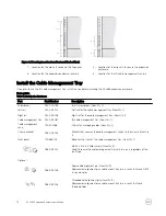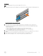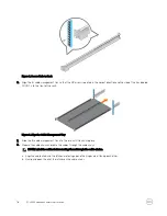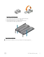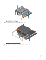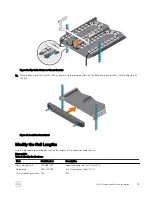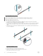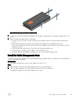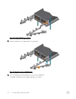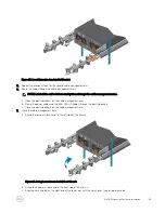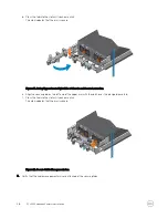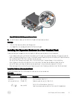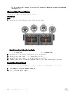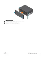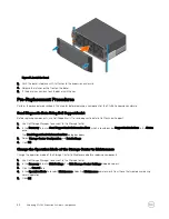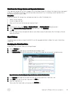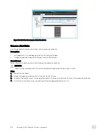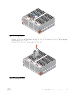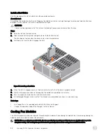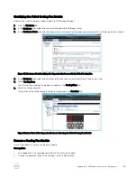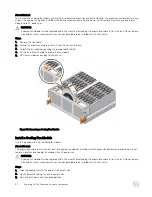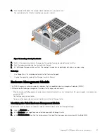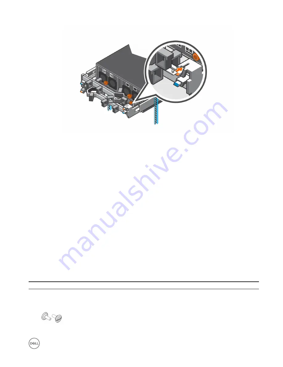
Figure 27. Verify that Cable Management Arms are Secure
9.
Connect the power cables and the Mini-SAS HD cables to the expansion enclosure.
Next steps
1.
Power on the expansion enclosure and storage system.
2.
Use SupportAssist to send diagnostic data to Dell Technical Support.
Installing the Expansion Enclosure in a Non-Standard Rack
Follow these best practice guidelines when installing the SCv360 expansion enclosure in a non-standard rack:
•
A non-standard rack might have PDUs that face into the rack. This might cause interference between the expansion enclosure
and/or rear cable management arms (if used). Carefully plan and route cables to minimize any interference. It might be necessary
to use a different type of PDU that is mounted in the main rack area.
•
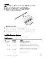
The rack rails have four adjustment ranges, 18-22", 22-26", 26-30", 30-34". The default length is the 22-26" setting.
•
After installing a rail, check the rail to make sure that it is level and in the correct location before installing the next rail.
•
Use the M5 screws, which align with both round and square holes, to secure all rails and components in the rack.
•
When securing rails to a rack, install the screws loosely to prevent cross threading, and tighten by hand. Do not over torque.
Install the Rails in a Nonstandard Rack
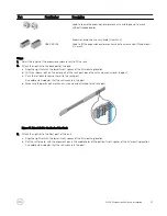
Perform the following steps to install the expansion enclosure rails in a nonstandard rack.
Prerequisite
Table 4. Identify the Hardware
Part
Part Number
Description
Screwdriver
034-000-193
6-in-1 screwdriver (Quantity: 1)
Left and right rack rails
100-569-001
Expansion enclosure rack rails (Quantity: 2)
036-028-018
M4-0.7 x 10 mm flathead screw (Quantity: 4)
Used to secure expansion enclosure rails to a rack with threaded holes
SCv360 Expansion Enclosure Installation
27


