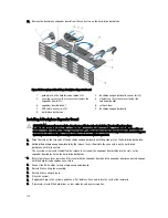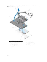
11. Angling the system board toward the back of the chassis to release the CMC connectors from the chassis slots,
slide the system board out of the chassis.
Figure 84. Removing and Installing the System Board
1.
system board
2.
system board handle
3.
spring-loaded screw
4.
guide pin
5.
midplane planar connectors (3)
6.
securing pins (2)
7.
system-board holder
126
Содержание PowerEdge M520
Страница 1: ...Dell PowerEdge VRTX Enclosure Owner s Manual Regulatory Model E22S Regulatory Type E22S001 ...
Страница 8: ...8 ...
Страница 34: ...34 ...
Страница 66: ...Figure 45 Securing the Power Cable Without Wheel Assembly 1 power cable 2 strap 66 ...
Страница 148: ...148 ...
Страница 151: ...Figure 94 System Board Connectors Back 1 midplane planar connectors 3 151 ...
Страница 152: ...152 ...
Страница 158: ...158 ...


