Basic Troubleshooting
2-7
I
nternal Visual Inspection
A simple visual inspection of a computer’s interior hardware can often lead to
the source of a problem, such as a loose expansion card, cable connector, or
mounting screw. When you perform the visual inspection, refer to “System Fea-
tures” in Chapter 1 to locate components in the inspection procedure.
To perform the internal visual inspection, follow these steps:
1. Turn off the computer, including any attached peripherals, and dis-
connect all the AC power cables from their power sources.
Wear a wrist grounding strap, and clip it to an unpainted metal surface, such
as the padlock loop on the back of the chassis. If a wrist grounding strap is
not available, touch an unpainted metal surface on the back of the computer
to discharge any static charge from your body.
2. Remove the computer cover as described in “Computer Cover” in
Chapter 4.
3. Verify that the chips, DIMMs, expansion card, and riser board are fully
seated in their sockets or connectors.
To ensure that the chips are fully seated in their sockets, press firmly on the
top of each chip.
To reseat the microprocessor, remove it from its socket and reinstall it as
described in “Microprocessor/Heat Sink Assembly” in Chapter 4.
To reseat a DIMM, remove it from its socket and reinstall it as described in
“DIMMs” in Chapter 4.
If you need to reseat an expansion card, remove it from its connector and
reinstall it as described in “Expansion Card” in Chapter 4.
If you need to reseat the riser board, remove it from the expansion-card cage
and reinstall it as described in “Riser Board” in Chapter 4.
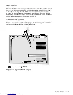
4. Verify that all jumpers are set correctly.
For information about these jumpers, see “System Board Jumpers” in
Chapter 1.
CAUTION: Before you proceed with the internal visual inspection
described in this section, ensure that the user has saved all open files and
exited all open application programs if possible.
WARNING: The microprocessor can get extremely hot. Be sure the
microprocessor/heat sink assembly has had sufficient time to cool
before you touch it.
While reseating the microprocessor/heat sink assembly, use a wrist
grounding strap or maintain contact with a metal surface on the
chassis.
Содержание OptiPlex N
Страница 1: ... HOO 2SWL3OH 1 6 VWHPV 6 59 0 18 ...
Страница 62: ...4 18 Dell OptiPlex N Systems Service Manual ...
Страница 71: ...Index 3 internal visual inspection 2 7 V video controller 1 4 visual inspection external 2 2 internal 2 7 ...
Страница 72: ...4 Dell OptiPlex N Systems Service Manual ...

