1-8
Dell OptiPlex N Systems Service Manual
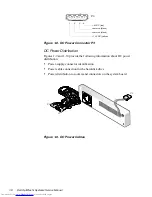
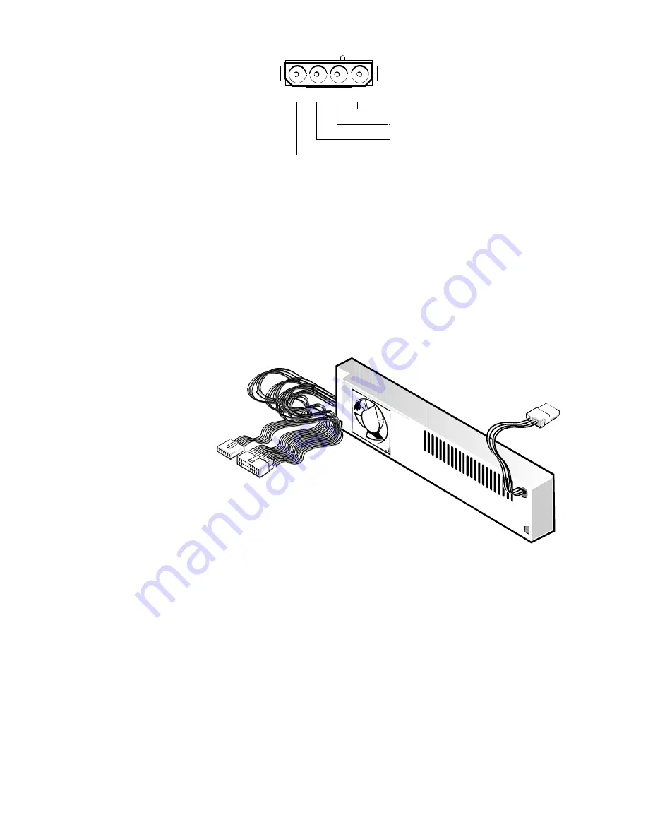
Figure 1-8. DC Power Connector P3
DC Power Distribution
Figures 1-9 and 1-10 provide the following information about DC power
distribution:
•
Power-supply connector identification
•
Power cable connection for the hard-disk drive
•
Power distribution to sockets and connectors on the system board
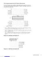
Figure 1-9. DC Power Cables
1
2
3
4
+5 VDC (red)
common (black)
common (black)
+12 VDC (yellow)
P3
P3
P2
P1
Содержание OptiPlex N
Страница 1: ... HOO 2SWL3OH 1 6 VWHPV 6 59 0 18 ...
Страница 62: ...4 18 Dell OptiPlex N Systems Service Manual ...
Страница 71: ...Index 3 internal visual inspection 2 7 V video controller 1 4 visual inspection external 2 2 internal 2 7 ...
Страница 72: ...4 Dell OptiPlex N Systems Service Manual ...


