Diagnostic light codes
Problem description
2,4
Memory or RAM (Random-Access Memory) failure
2,5
Invalid memory installed
2,6
System-board or chipset error
2,7
Display failure
2,8
LCD power rail failure. Replace system board
3,1
Coin-cell battery failure
3,2
PCI, video card/chip failure
3,3
Recovery image not found
3,4
Recovery image found but invalid
3,5
Power-rail failure
3,6
System BIOS Flash incomplete
3,7
Management Engine (ME) error
Camera status light:
Indicates whether the camera is in use.
•
Solid white — Camera is in use.
•
Off — Camera is not in use.
Caps Lock status light:
Indicates whether Caps Lock is enabled or disabled.
•
Solid white — Caps Lock enabled.
•
Off — Caps Lock disabled.
M-BIST
M-BIST (Built In Self-Test) diagnostics tool, featuring improved accuracy in system board failures.
NOTE:
M-BIST can be manually initiated before POST (Power On Self Test).
How to run M-BIST
NOTE:
M-BIST must be initiated on the system from a power-off state either connected to AC power or with battery
only.
1. Press and hold both the
M
key on the keyboard and the
power button
to initiate M-BIST.
2. With both the
M
key and the
power button
held down, the battery indicator LED may exhibit two states:
a. OFF: No fault detected with the system board
b. AMBER: Indicates a problem with the system board
LCD Built-in Self Test
Overview : LCD Built-in Self Test (BIST)
Dell laptops have a built-in diagnostic tool that helps you determine if the screen abnormality you are experiencing is an inherent problem
with the LCD (screen) of the Dell laptop or with the video card (GPU) and PC settings .
When you notice screen abnormalities like flickering, distortion, clarity issues, fuzzy or blurry image, horizontal or vertical lines, color fade
etc., it is always a good practice to isolate the LCD (screen) by running the Built-In Self Test (BIST).
How to invoke LCD BIST Test
1. Power off the Dell laptop.
Troubleshooting
91
Содержание Latitude 9410
Страница 1: ...Dell Latitude 9410 Service Manual Regulatory Model P110G Regulatory Type P110G001 ...
Страница 12: ...Major components of your system 1 Base cover 2 Heatsink shield 3 12 Major components of your system ...
Страница 22: ...2 Press along the edges of the base cover until it clicks into place 22 Removing and installing components ...
Страница 23: ...3 Tighten the 10 captive screws to secure the base cover to the computer Removing and installing components 23 ...
Страница 36: ...5 Place the metal shield on the WWAN card 36 Removing and installing components ...
Страница 44: ...8 Adhere the Mylar sheet on the system board 1 Connect the battery cable 44 Removing and installing components ...
Страница 49: ...4 Remove the metal foil from the heatsink shield Removing and installing components 49 ...
Страница 50: ...5 Remove the heatsink shield from the system board 50 Removing and installing components ...
Страница 53: ...3 Place the heatsink shield on the heatsink Removing and installing components 53 ...
Страница 54: ...4 Adhere the metal foils on the heatsink shield 54 Removing and installing components ...
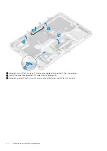
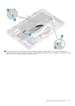
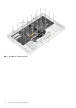
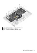
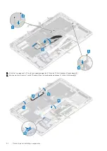
Страница 80: ...8 Lift the keyboard off the palmrest assembly 80 Removing and installing components ...
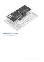
Страница 81: ...Installing the keyboard 1 Place the keyboard on the palmrest assembly Removing and installing components 81 ...


