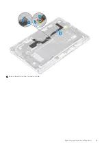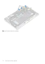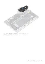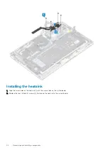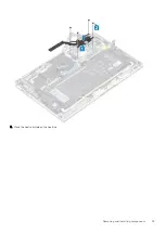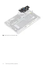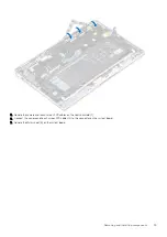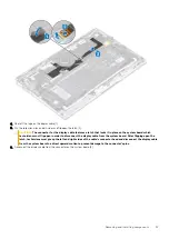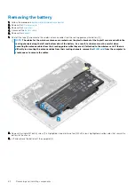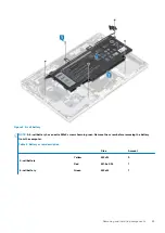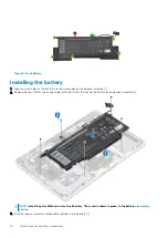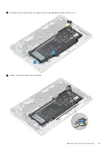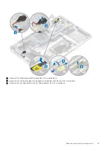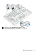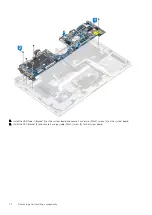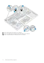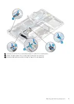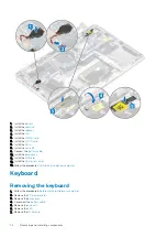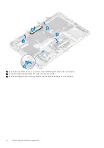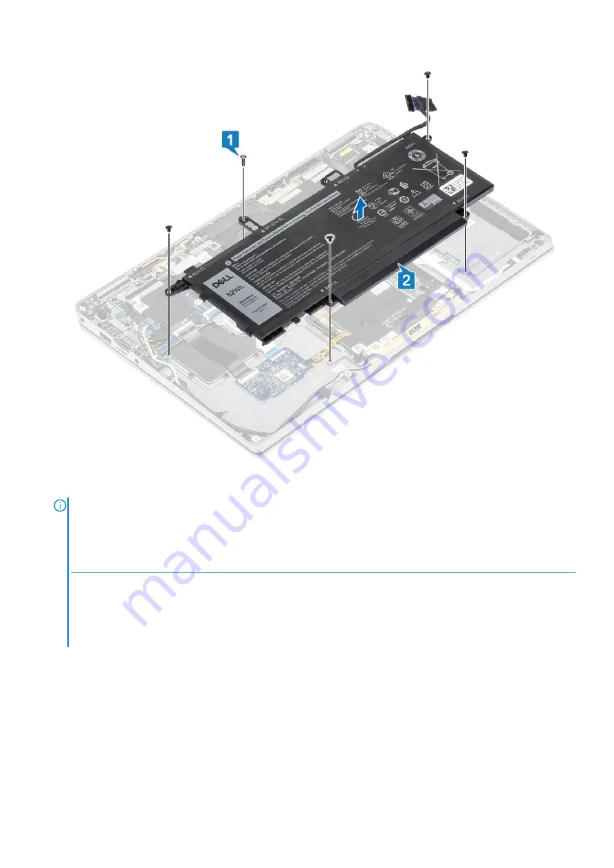
Figure 2. 4-cell battery
NOTE:
A 6-cell battery has an extra M2x4 screw shown in green. Remove the screw before removing the battery
from the computer.
Table 8. Battery screw description
Size
Amount
4-cell battery
Yellow
M2x3L
5
Red
M1.6x4.5L
1
6-cell battery
Green
M2x4L
1
Removing and installing components
63
Содержание Latitude 9410
Страница 1: ...Dell Latitude 9410 Service Manual Regulatory Model P110G Regulatory Type P110G001 ...
Страница 12: ...Major components of your system 1 Base cover 2 Heatsink shield 3 12 Major components of your system ...
Страница 22: ...2 Press along the edges of the base cover until it clicks into place 22 Removing and installing components ...
Страница 23: ...3 Tighten the 10 captive screws to secure the base cover to the computer Removing and installing components 23 ...
Страница 36: ...5 Place the metal shield on the WWAN card 36 Removing and installing components ...
Страница 44: ...8 Adhere the Mylar sheet on the system board 1 Connect the battery cable 44 Removing and installing components ...
Страница 49: ...4 Remove the metal foil from the heatsink shield Removing and installing components 49 ...
Страница 50: ...5 Remove the heatsink shield from the system board 50 Removing and installing components ...
Страница 53: ...3 Place the heatsink shield on the heatsink Removing and installing components 53 ...
Страница 54: ...4 Adhere the metal foils on the heatsink shield 54 Removing and installing components ...
Страница 80: ...8 Lift the keyboard off the palmrest assembly 80 Removing and installing components ...
Страница 81: ...Installing the keyboard 1 Place the keyboard on the palmrest assembly Removing and installing components 81 ...

