SupportAssist Error Messages
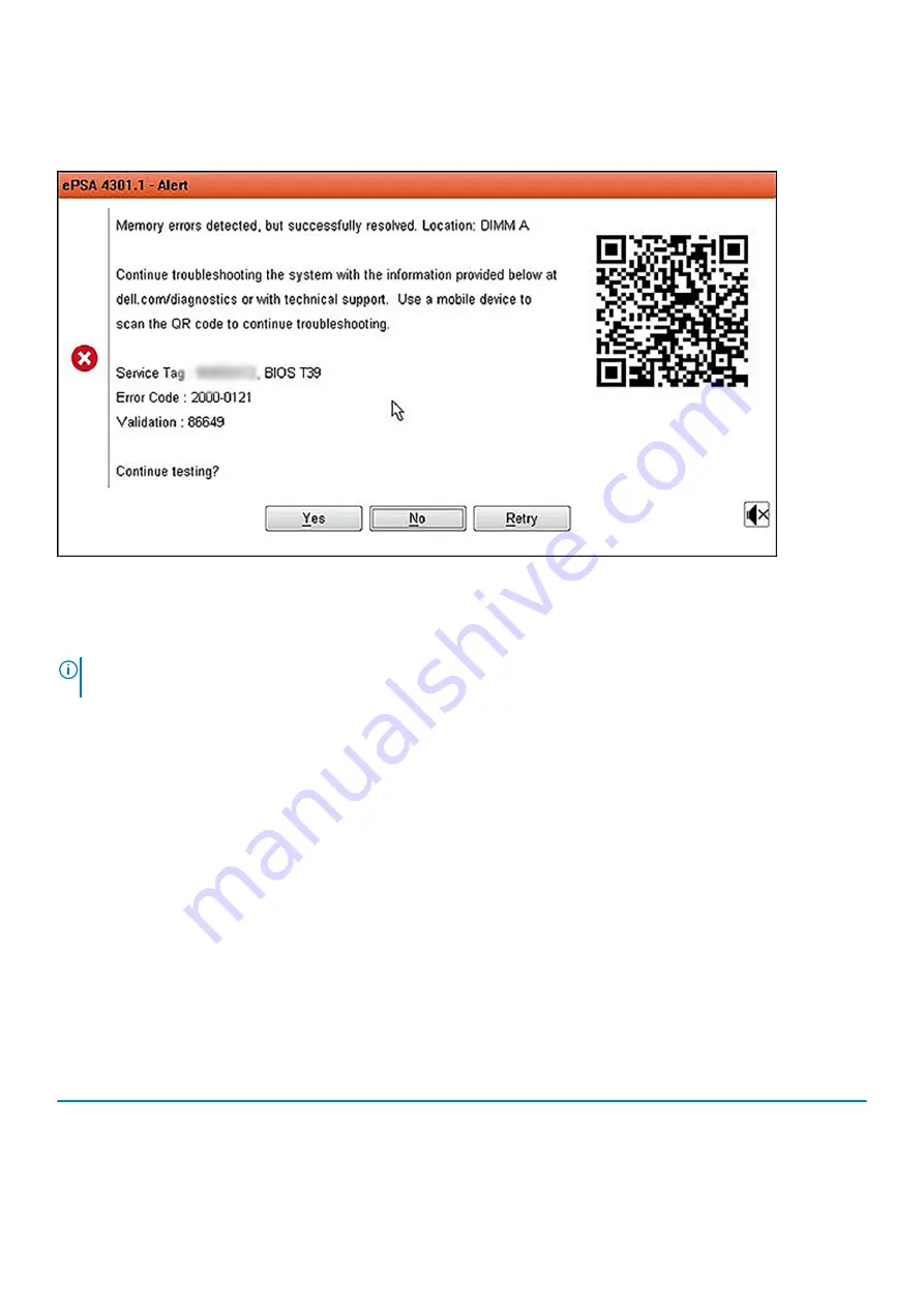
When the Dell SupportAssist Diagnostic detects an error while running, it will pause the test and the following window is displayed:
•
By responding Yes, the diagnostic will continue testing the next device and the error details will be available in the summary report.
•
By responding No, the diagnostic will stop testing the remaining untested device.
•
By responding Retry, the diagnostic will ignore the error and rerun the last test.
Capture the error code with Validation code or Scan QR code and Contact Dell.
NOTE:
Some tests for specific devices require user interaction. Always ensure that you are present before the computer
when the diagnostic tests are performed
System diagnostic lights
Battery-status light
Indicates the power and battery-charge status.
Solid white
— Power adapter is connected and the battery has more than 5 percent charge.
Amber
— Computer is running on battery and the battery has less than 5 percent charge.
Off
•
Power adapter is connected and the battery is fully charged.
•
Computer is running on battery and the battery has more than 5 percent charge.
•
Computer is in sleep state, hibernation, or turned off.
The power and battery-status light blinks amber along with beep codes indicating failures.
For example, the power and battery-status light blinks amber two times followed by a pause, and then blinks white three times followed by
a pause. This 2,3 pattern continues until the computer is turned off indicating no memory or RAM is detected.
The following table shows different power and battery-status light patterns and associated problems.
Table 9. LED codes
Diagnostic light codes
Problem description
2,1
Processor failure
2,2
System board: BIOS or ROM (Read-Only Memory) failure
2,3
No memory or RAM (Random-Access Memory) detected
90
Troubleshooting
Содержание Latitude 9410
Страница 1: ...Dell Latitude 9410 Service Manual Regulatory Model P110G Regulatory Type P110G001 ...
Страница 12: ...Major components of your system 1 Base cover 2 Heatsink shield 3 12 Major components of your system ...
Страница 22: ...2 Press along the edges of the base cover until it clicks into place 22 Removing and installing components ...
Страница 23: ...3 Tighten the 10 captive screws to secure the base cover to the computer Removing and installing components 23 ...
Страница 36: ...5 Place the metal shield on the WWAN card 36 Removing and installing components ...
Страница 44: ...8 Adhere the Mylar sheet on the system board 1 Connect the battery cable 44 Removing and installing components ...
Страница 49: ...4 Remove the metal foil from the heatsink shield Removing and installing components 49 ...
Страница 50: ...5 Remove the heatsink shield from the system board 50 Removing and installing components ...
Страница 53: ...3 Place the heatsink shield on the heatsink Removing and installing components 53 ...
Страница 54: ...4 Adhere the metal foils on the heatsink shield 54 Removing and installing components ...
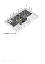
Страница 80: ...8 Lift the keyboard off the palmrest assembly 80 Removing and installing components ...
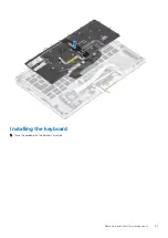
Страница 81: ...Installing the keyboard 1 Place the keyboard on the palmrest assembly Removing and installing components 81 ...

