NOTE:
System configurations ordered with finger print reader there are two screws securing the finger print reader
bracket to the palmrest assembly.
2. Disconnect the power button with finger print reader cable from the I/O daughterboard.
For system units ordered with WWAN card, disconnect and remove the antennae cables from the WWAN card on the I/O
daughterboard.
3. Remove two M2x3.5 screws on the F-beam FPC connector and remove it from the system board.
4. Lift and remove the I/O daughterboard from the system unit.
Installing the I/O board
Prerequisites
If you are replacing a component, remove the existing component before performing the installation procedure.
About this task
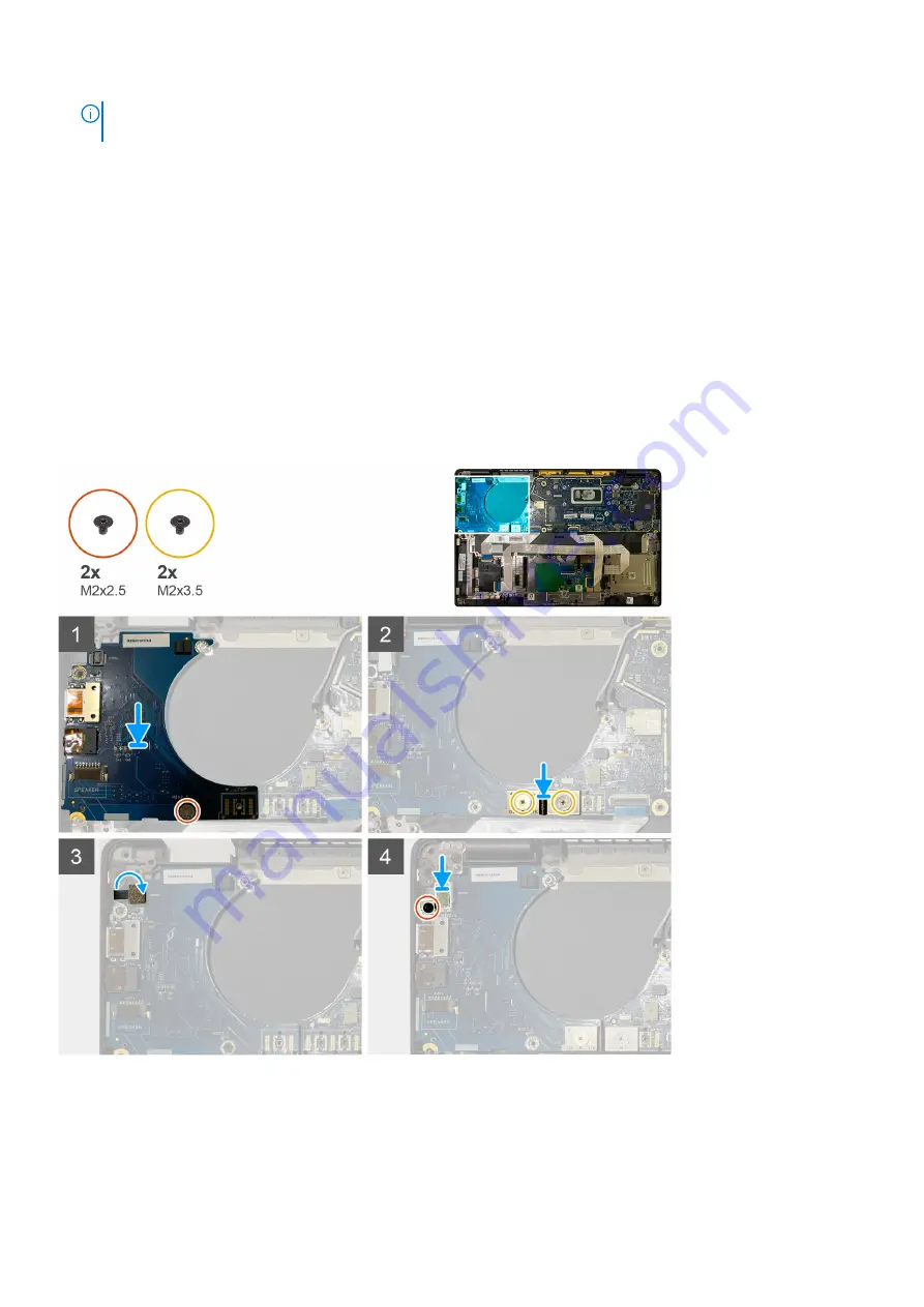
The following images indicate the location of the I/O board and provide a visual representation of the installation procedure.
Steps
1. Align the screw hole with that on the palmrest assembly and replace the I/O daughterboard into its slot on the palmrest assembly.
2. Connect the F-beam FPC connector to the I/O board and secure it using the two M2x3.5 screws.
3. Connect the power button cable to the I/O daughterboard.
4. Replace the two M2x2.5 screws securing the power button to the I/O board.
38
Removing and installing components
Содержание Latitude 7310
Страница 10: ...10 Removing and installing components ...
Страница 11: ...Removing and installing components 11 ...
Страница 13: ...Removing and installing components 13 ...
Страница 17: ...Figure 1 2230 SSD Removing and installing components 17 ...
Страница 19: ...Figure 3 2230 SSD Removing and installing components 19 ...
Страница 44: ...44 Removing and installing components ...


