background image

Back to Contents Page


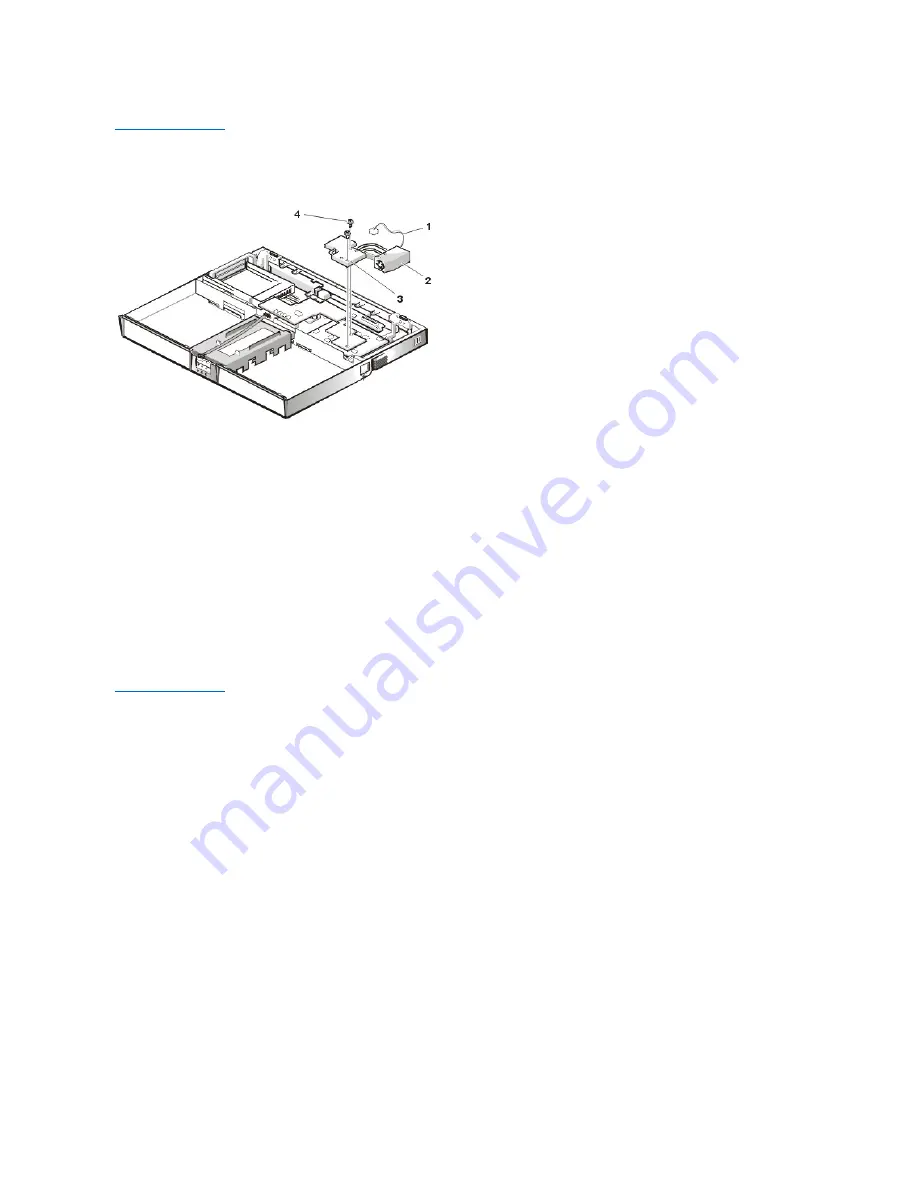
Heat Exchanger/Fan Removal: Dell™ Inspiron™ 7500


****New artwork pending


To remove the heat exchanger/fan, follow these steps:


1.

Remove the (2) 5-mm screws securing the heat exchanger.


2.

Disconnect the fan cable from connector JP17 on the system board.


3.

Remove the heat exchanger/fan.


4.

Inspect the 2 thermal pads on the bottom of the heat exchanger and replace them if necessary.


To remove the heat exchanger/fan without removing the palmrest assembly, follow these steps.


1.

Remove the (2) 5-mm screws securing the heat exchanger.


2.

Disconnect the fan cable from connector JP17 on the system board.


3.

Lift the heat exchanger and rotate it upward.


4.

Slide the heat exchanger/fan toward the front of the computer until the fan is completely clear of the overhanging palmrest plastic.


5.

Lift the heat exchanger/fan out at an angle.


6.

Inspect the 2 thermal pads on the bottom of the heat exchanger and replace them if necessary.


When reinstalling the heat exchanger/fan, be sure to reconnect the fan cable to JP17; if you have an internal modem, there is an identical connector 
(JP2) next to JP17. The modem connector is color-coded red.


Back to Contents Page


Содержание Inspiron 7500

Страница 1: ...trademark of Intel Corporation Adobe is a trademark of Adobe Systems Incorporated which may be registered in certain jurisdictions Other trademarks and trade names may be used in this document to refer to either the entities claiming the marks and names or their products Dell Computer Corporation disclaims any proprietary interest in trademarks and trade names other than its own Initial release 20...

Страница 2: ...board 2 Remove the 4 6 mm screws from the sides of the mounting brackets 3 Remove the brackets from the LCD panel To remove the 13 3 inch LCD panel from the carrier tray follow these steps 1 Remove any Kapton tape covering the CCFL cable 2 Gently pull the cable out of its connector 3 Remove any Kapton tape from the LCD wire harness 4 Disconnect the LCD wire harness from the LCD panel 5 Lift the LC...

Страница 3: ...board and LCD panel 4 Loosen the 3 mm screw securing the inverter board 5 Lift the LCD panel LCD brackets and carrier tray as a unit out of the back cover Rotate upward from the bottom of the panel because the top slides underneath the plastic hooks 6 Remove the hinges which were previously held in place by pressure and screws To remove the inverter board follow these steps 1 Remove the 3 mm screw...

Страница 4: ...ve the hinges which were previously held in place by pressure and screws To remove the LCD brackets from the LCD panel follow these steps 1 Remove the 4 4 mm screws from the sides of the LCD brackets 2 Remove the brackets from the LCD panel To remove the LCD panel from the carrier tray follow these steps 1 Lift the inverter board shield pull it slightly away from the panel to expose the cabling an...

Страница 5: ...he assembly off the computer base To remove the front bezel follow these steps 1 Remove the two rubber screw covers and screws on the LCD near the hinge Remove the remaining three plastic screw covers and screws one on either side and one in the front 2 With all screws removed unsnap the front bezel from the back cover and remove the bezel from the assembly To remove the LCD panel hinges and inver...

Страница 6: ...Back to Contents Page AC Adapter Dell Inspiron 7500 ...

Страница 7: ...Back to Contents Page Audio Jacks Dell Inspiron 7500 ...

Страница 8: ...layers and VCRs to the line in connector on the left See your Microsoft Windows 98 documentation for the location of sound application programs such as mixers and volume control You can control the sound coming from the external speakers and the computer s integrated speakers with the volume control dial You can also use the keyboard to adjust the volumes Press to lower the volume Press to increas...

Страница 9: ...plastic case and have removed the PC Card cage from the system board To remove the audio card and audio thermal shield follow these steps 1 Gently pull the audio card off of connectors JP12 and JP13 on the system board Do not rock the card to remove it because this may damage the connectors 2 Remove the 10 mm screw securing the audio thermal shield and then remove the shield ...

Страница 10: ...Back to Contents Page Component Locations Back View Dell Inspiron 7500 ...

Страница 11: ...l shield display assembly and palmrest assembly have been removed Back to Contents Page Base Assembly Base Assembly Component Removal PC Card Heat Sink Removal Heat Exchanger Fan Removal DC DC Board Removal Processor Board and Memory Module Removal Hinge Saddle Removal RJ 11 Card Removal System Board Removal PC Card Cage Removal Audio Card and Audio Thermal Shield Removal Latch Assembly Removal ...

Страница 12: ...Back to Contents Page Battery Charge Gauge Dell Inspiron 7500 ...

Страница 13: ...Back to Contents Page Removing and Installing a Battery Dell Inspiron 7500 ...

Страница 14: ...ff of the top 2 screws 2 Remove the 4 6 mm screws from the front bezel 3 Unsnap the front bezel from the back cover and remove it from the assembly Carefully insert your fingers between the LCD panel and the bezel Roll the plastic up slightly to insert your fingers further in and then lift upward to free the snaps Start at the middle bottom and then work around When replacing the bezel ensure that...

Страница 15: ...k to the unlocked position see Figure 1 and slide the latch release in the direction of the arrow Keep holding the latch release with one hand while pulling the device out of the media bay with the other Figure 1 Removing Devices From the Media Bay 4 Install the new device in the media bay Insert the device into the media bay and push the latch lock back into the locked position The label on the d...

Страница 16: ...e from its packaging Save the original packaging to use when storing or shipping the hard disk drive 6 Slide the new drive into place NOTE The computer s BIOS may not support hard disk drives obtained from vendors other than Dell Dell does not guarantee compatibility or provide support for hard disk drives obtained from other sources NOTICE To prevent data loss shut down your computer before remov...

Страница 17: ...tion of sound application programs such as mixers and volume control You can control the sound coming from the external speakers and the computer s integrated speakers with the volume control dial You can also use the keyboard to adjust the volumes Press to lower the volume Press to increase the volume Press to enable or disable both the integrated and external speakers See Utilities and Drivers f...

Страница 18: ...se from Dell you may need to install device drivers separately to use the mouse This software is usually included with mouse installation kits Touch Pad The PS 2 compatible touch pad detects the position of your finger over a touch sensitive area and provides the computer full mouse functionality The touch pad s two buttons correspond to the left and right buttons on a standard mouse When Keypad I...

Страница 19: ...for high performance graphics Figure 7 PC Card Slots The computer supports two Type I two Type II or one Type III PC Card including such memory devices as static random access memory SRAM cards that emulate diskettes RAM cards one time programmable OTP ROM cards and Advanced Technology Attachment ATA cards that emulate integrated drive electronics IDE hard disk drives Also supported are input outp...

Страница 20: ... If you are using the Microsoft Windows 98 operating system click the Start button point to Settings and then click Control Panel Double click the PC Card to open the PC Card Properties window For more information check the documentation that came with your operating system You can also double click the PC Card icon on the Windows 98 desktop External Monitor Use the 15 pin video connector to attac...

Страница 21: ...Back to Contents Page NOTE When the external monitor and built in display are used simultaneously the refresh rate is always 60 hertz Hz ...

Страница 22: ... otherwise indicated to perform a single function Example Ctrl Alt Enter l Commands presented in lowercase bold are for reference purposes only and are not intended to be typed when referenced Example Use the format command to In contrast commands presented in the Courier New font are part of an instruction and intended to be typed Example Type format a to format the diskette in drive A l Filename...

Страница 23: ...ge DC DC Board Removal Dell Inspiron 7500 To remove the DC DC board gently pull the DC DC board off of connectors JP11 and JP16 on the system board Do not rock the board to remove it because this may damage the connectors ...

Страница 24: ...A 1 Remove the left hinge cover Remove the two Phillips screws on the LCD wire harness on JP3 Use a dental pick or flat blade screwdriver to pry each end of the connector to release it 2 Close the display 3 Remove the 4 6 mm screws that secure the 2 hinges 4 Unlatch the display assembly and lift the assembly off the computer base Display Assembly Component Removal Back to Contents Page Display Ass...

Страница 25: ...oft Windows desktop and then click Run 4 Type regsvr32 popup ocx and then press Enter 5 Click OK when the installation is complete 6 Right click the following link to the Help file Dell Inspiron 7500 System Help chm 846 KB 7 Click Save Target As in Microsoft Internet Explorer or Save Link As in Netscape Navigator and specify a location on your hard disk drive Viewing the Help File To view the Help...

Страница 26: ...Back to Contents Page ...

Страница 27: ...Back to Contents Page Drivers Dell Inspiron 7500 Reinstalling Utilities and Drivers for Windows 98 Reinstalling Utilities and Drivers for Windows NT ...

Страница 28: ...drive before you install any device drivers To install Windows 98 perform the following steps 1 Insert the Microsoft Boot Disk Windows 98 Series diskette into the diskette drive 2 Restart the computer 3 When the Microsoft Windows 98 Startup menu appears insert the Microsoft Windows 98 CD into the CD ROM or DVD ROM drive 4 Select Start Windows 98 Setup from CD ROM and press Enter The Setup program ...

Страница 29: ... Welcome to Windows 98 screen appears click the x in the upper right corner of the screen to close it and continue with the installation 4 Click the Start button and then click Run 5 In the Run dialog box type x win98 video setup exe where x is the CD ROM or DVD ROM drive The CD ROM or DVD ROM drive letter is usually D 6 Click OK 7 When prompted to restart click Finish The computer restarts automa...

Страница 30: ...to close it and continue with the installation 4 Click the Start button and then click Run 5 In the Run dialog box type x win98 modem setup exe where x is the CD ROM or DVD ROM drive letter The CD ROM or DVD ROM drive letter is usually D 6 Click OK 7 At the Welcome Screen click Next The internal modem files are copied to your hard disk drive The New Hardware Found window appears the driver is inst...

Страница 31: ...memory in your computer and adds 2 megabytes MB to handle additional system requirements 8 Follow the instructions on your screen to create the save to disk suspend file To check the size of the save to disk suspend file type phdisk info at the MS DOS prompt and press Enter To delete the save to disk suspend file type phdisk delete file and press Enter 9 Remove the System Software CD and press Ctr...

Страница 32: ...e 2 of 4 in drive A appears type C to exit to MS DOS Leave the Dell Diagnostics and Utilities for Inspiron 7500 diskette number 1 in the diskette drive 3 At the A prompt type phdisk create partition and press Enter The utility calculates the size of the file in kilobytes KB based on the amount of system memory and video memory in your computer and adds 2 megabytes MB to handle additional system re...

Страница 33: ... of your computer 1 Log on as Administrator 2 Insert the System Software CD into the CD ROM drive 3 Click the Start button and then click Run 4 In the Run dialog box type x winnt audio setup exe where x is the DVD ROM drive letter 5 Click OK 6 At the Welcome screen click Next 7 At the Main Menu the Install radio button is selected Click Next The audio files are copied to your hard disk drive 8 Whe...

Страница 34: ...wer Management icon appears in the Control Panel after you install the utility 1 Log on as Administrator 2 Insert the System Software CD into the CD ROM drive 3 Double click the My Computer icon and then double click the CD ROM drive icon 4 Double click the WinNT folder and then double click the APM folder 5 Double click Setup The Softex Power Management Control Setup screen appears and then the S...

Страница 35: ...iver if the computer does not have an internal modem installed 1 Log on as Administrator 2 Insert the System Software CD into the CD ROM drive 3 Double click the My Computer icon and then double click the CD ROM drive icon 4 Double click the WinNT folder and then double click the Modem folder 5 Double click Setup The Installing Modem Drivers window appears At the Modem Installation window click Ne...

Страница 36: ... Right click and hold 7500help and drag it to the Windows desktop 5 Release the right mouse button 6 Left click Copy Here 7 Double click the 7500help icon to access the system Help Back to Contents Page ...

Страница 37: ...hed to the monitor connect it to the monitor also The video image can be displayed on an external monitor on the computer s display or on both simultaneously To toggle between the three display modes press Fn F8 If the external monitor is turned off when you boot the computer and if the Video Display Device category is set to CRT Mode in the Main menu of the Setup program the computer sends the vi...

Страница 38: ...Exploded View of 13 3 Inch Display Assembly Dell Inspiron 7500 ...

Страница 39: ...Exploded View of 14 1 Inch Display Assembly Dell Inspiron 7500 ...

Страница 40: ...Back to Contents Page Exploded View of 15 Inch SXGA Display Assembly Dell Inspiron 7500 New artwork pending ...

Страница 41: ...Back to Contents Page Exploded View of 15 Inch XGA Display Assembly Dell Inspiron 7500 New artwork pending Back to Contents Page ...

Страница 42: ...Back to Contents Page Exploded View of 15 4 Inch SXGA Display Assembly Dell Inspiron 7500 New artwork pending ...

Страница 43: ...Back to Contents Page Exploded View of Base Assembly Dell Inspiron 7500 New artwork pending Back to Contents Page ...

Страница 44: ...Back to Contents Page Exploded View of Computer Dell Inspiron 7500 ...

Страница 45: ...Back to Contents Page Exploded View of Palmrest Assembly Dell Inspiron 7500 Back to Contents Page ...

Страница 46: ... the USB connector If you attach a USB mouse to the computer you do not need to reboot the computer in order to use the mouse The touch pad device drivers that Dell installed on your hard disk drive work with a PS 2 mouse serial mouse or USB mouse from Dell If you did not receive your mouse from Dell you may need to install device drivers separately to use the mouse This software is usually includ...

Страница 47: ...Back to Contents Page Component Locations Front View Dell Inspiron 7500 New artwork pending ...

Страница 48: ...2 5x3L 8X K head M2x3L Keyboard 4X pan head M2 5x20L LCD panel 15 inch XGA 1X 0143E SCR M2 5x 45P 3FP ZK 2X 7043E SCR M2 5x 45 10FP ZK NL 6X 8043E SCR 2 5x 45 6P ZK NL LCD panel 15 inch SXGA 8X 3319U SCR M2x3 KSH MSCR CPS LKG 2X 7043E SCR M2 5x 45 10FP ZK NL LCD panel 15 4 inch SXGA 2X 0300U SCR 2 5x8 KSH MSCR CPS 8X 9200U SCR M2x4 KSH MSCR CPS Thermal shield 1X K head M2 5x4L 4X flat head M2x4L D...

Страница 49: ...ponent Locations Back View AC Adapter Removing and Installing a Battery From the MegaBay Battery Charge Gauge Removing Devices From the Media Bay Removing the Hard Disk Drive Removing the Memory Module Touch Pad Audio Jacks PC Card Slots Embedded Numeric Keypad Security Cable Slot I O Connectors 30 Cone of Infrared Light ...

Страница 50: ... drive assembly See step 7 of Precautionary Measures 2 Remove the 4 3 mm screws securing the hard disk drive inside the carrier 3 Remove the hard disk drive from the carrier Turn the carrier over with one hand and let the drive fall out of the carrier into your other hand 4 Remove the metal carrier from the plastic cover The metal carrier is held in the plastic cover by 2 tabs on each end Carefull...

Страница 51: ...s that you have removed the palmrest assembly from the base assembly To remove the hard disk drive heat shield follow these steps 1 Place the palmrest assembly face down 2 Remove the 5 4 mm screws securing the hard disk drive heat shield 3 Remove the hard disk drive heat shield Back to Contents Page ...

Страница 52: ... steps 1 Remove the 2 5 mm screws securing the heat exchanger 2 Disconnect the fan cable from connector JP17 on the system board 3 Lift the heat exchanger and rotate it upward 4 Slide the heat exchanger fan toward the front of the computer until the fan is completely clear of the overhanging palmrest plastic 5 Lift the heat exchanger fan out at an angle 6 Inspect the 2 thermal pads on the bottom o...

Страница 53: ...he left and right hinge saddles 2 Remove the 4 4 mm screws from the back of the computer above the ports 3 Remove the 10 mm screw and 20 mm screw from the right hinge saddle and remove the saddle 4 Remove the 10 mm screw and 20 mm screw from the left hinge saddle and remove the saddle 5 Disconnect the LED cable from connector J6 on the system board 6 Remove the 6 mm screw from the plastic frame re...

Страница 54: ...Back to Contents Page I O Connectors Dell Inspiron 7500 ...

Страница 55: ... a 30 cone of infrared light Start the data communications software on both devices and then begin transferring files Read the documentation that came with your compatible device to make sure you operate it correctly Modem Port The Modem Port option appears only if your computer has an integrated modem This option allows you to map the address of the port to avoid address conflicts with other devi...

Страница 56: ...or compatibility with the PS 2 standard Support for the EPP feature improves network adapter performance adapters connect to the computer s parallel port and require the appropriate software drivers from the adapter s manufacturer If you reconfigure your hardware you may need pin number and signal information for the serial connector Pin Assignments for the Parallel Connector Pin Signal I O Defini...

Страница 57: ...or Pin Assignments for the PS 2 Connector 11 BUSY I Busy 12 PE I Paper end 13 SLCT I Select 14 AFD O Automatic feed 15 ERR I Error 16 INIT O Initialize printer 17 SLIN O Select in 18 25 N A N A Signal ground Shell N A N A Frame ground Pin Signal I O Definition 1 RED O Red video 2 GREEN O Green video 3 BLUE O Blue video 4 NC N A No connection 5 GND N A Signal ground 6 GND N A Signal ground 7 GND N ...

Страница 58: ...h your system to the S video TV out connector 2 Connect the other end of the cable to the television s composite cable Back to Contents Page Pin Signal I O Definition 1 EXK_MSDATA I O External keyboard keypad mouse data 2 NC N A No connection 3 GND N A Signal ground 4 EXK_MSPWR N A External keyboard keypad mouse supply voltage 5 EXK_MSCLK I O External keyboard keypad mouse clock 6 NC N A No connec...

Страница 59: ...is procedure assumes that you have removed the palmrest assembly from the base assembly To remove the IR board follow these steps 1 Remove the 2 4 mm screws securing the IR board 2 Disconnect the IR cable from connector JP2 on the IR board 3 Remove the IR board ...

Страница 60: ...Back to Contents Page 30 Cone of Infrared Light Dell Inspiron 7500 ...

Страница 61: ...panel below the display latch and 2 on the left side l System power Solid green light when the system is on blinking green light when the system is in suspend state l Hard disk drive activity Blinking green light as the drive is being accessed l Battery status Solid green light when the battery is fully charged Blinking green light when the battery is charging No light when the battery is discharg...

Страница 62: ...ft Power Button Under normal circumstances you should only use the power button to turn on the computer or to resume from save to disk suspend or standby mode To shut down the computer click the Start button in the Microsoft Windows 98 operating system and then click Shut Down If the computer is hung and the operating system does not respond press and hold the power button until the system turns o...

Страница 63: ...it When free lift the top of the keyboard slightly to clear the palmrest assembly 4 Slide the keyboard toward the display assembly to release the front edge of the keyboard from the palmrest assembly 5 Rotate the bottom of the keyboard up toward the display assembly to expose the keyboard cable 6 Disconnect the keyboard cable from ZIF connector JP14 on the system board Use the pick to pry up the l...

Страница 64: ...Back to Contents Page Embedded Numeric Keypad Dell Inspiron 7500 ...

Страница 65: ... the LED board 2 Remove the 4 mm screw securing the LED board to the plastic base 3 Remove the LED board 4 Remove the 2 4 mm screws holding the latch cover for the MegaBay and Media bay 5 Remove the latch cover 6 Remove the center lock over the 2 latches with springs 7 Remove each spring and latch Be careful not to lose the small springs Back to Contents Page ...

Страница 66: ... remove the LVDS board follow these steps 1 Remove the 4 mm screw securing the LVDS board 2 Gently pull the LVDS board off of connectors JP9 and JP8 on the system board Do not rock the board to remove it because this may damage the connectors ...

Страница 67: ...work pending This procedure assumes that you have removed the PC Card heat sink and hinge saddles To remove the system board follow these steps 1 Remove the 3 4 mm screws from the bottom of the computer 2 Remove the system board from the bottom case Back to Contents Page ...

Страница 68: ... Guidelines Valid Memory Configurations Removing and Installing Memory Upper Memory Map Conventional Memory Map Slot 1 Slot 2 Total 32 MB 32 MB 64 MB 32 MB 64 MB 96 MB 32 MB 128 MB 160 MB 32 MB 192 MB 224 MB 32 MB 256 MB 288 MB 64 MB 32 MB 96 MB 64 MB 64 MB 128 MB 64 MB 128 MB 192 MB 64 MB 192 MB 256 MB 64 MB 256 MB 320 MB 128 MB 32 MB 160 MB 128 MB 64 MB 192 MB 128 MB 128 MB 256 MB 128 MB 192 MB ...

Страница 69: ...s to spread the inner metal tabs of the socket when you are installing or removing a memory module 6 If you are replacing one or more memory modules remove the memory module s as shown in the figure above Using your fingernails carefully spread apart the inner metal tabs of the memory module socket just far enough for the memory module to disengage from the socket the module should pop up slightly...

Страница 70: ... if you installed a new hard disk drive if you removed the file or if you are rebuilding a corrupted hard disk drive perform the following steps 1 Save and close any open files exit any open application programs and shut down the computer 2 Insert the Microsoft Boot Disk Windows 98 Series diskette into the diskette drive 3 When the Microsoft Boot Disk Windows 98 Startup Menu appears press the down...

Страница 71: ... 2 mouse data area 000000 09FBFF Conventional memory Segment Address Range Use 0 00000h 003FFh Interrupt vector table 00400h 004FFh BIOS data area 00500h 005FFh MS DOS work area 00600h 0FFFFh User memory 1 10000h 1FFFFh User memory 2 20000h 2FFFFh User memory 3 30000h 3FFFFh User memory 4 40000h 4FFFFh User memory 5 50000h 5FFFFh User memory 6 60000h 6FFFFh User memory 7 75000h 7FFFFh User memory ...

Страница 72: ...the carrier into your other hand To remove the side mounting bracket from the CD ROM DVD ROM drive follow these steps 1 Remove the 2 2 5 mm screws from the side of the CD ROM DVD ROM drive 2 Remove the side mounting bracket To remove the diskette drive from the plastic carrier follow these steps 1 Remove the 2 3 mm screws from the top of the metal shielding carrier 2 Remove the 2 3 mm screws from ...

Страница 73: ...When reassembling the diskette drive be sure that the bottom of the metal shielding carrier sits inside the groove at the front of the plastic carrier Back to Contents Page ...

Страница 74: ... Inspiron 7500 Video I O Memory Power Sources Storage Devices Touch Pad Audio Devices PC Cards Using the Embedded Numeric Keypad Using an External Monitor Using an External Keyboard Keypad or Mouse Power Conservation Passwords and Security ...

Страница 75: ...ure that Num Lk is off Press and hold Fn and the corresponding key as displayed in the following list Back to Contents Page When Keypad Is Activated Number Lock Indicator ON Function Fn key Enables the lowercase letter or primary function of that specific key Fn Shift key Enables the uppercase letter or shift function of that specific key When Keypad Is Deactivated Function Fn j Performs the same ...

Страница 76: ...100 640 x 480 32 bit 100 800 x 600 256 colors 100 800 x 600 16 bit 100 800 x 600 24 bit 100 800 x 600 32 bit 100 1024 x 768 256 colors 100 1024 x 768 16 bit 100 1024 x 768 24 bit 100 1024 x 768 32 bit 100 1280 x 1024 256 colors 100 1280 x 1024 16 bit 100 1280 x 1024 24 bit 100 1400 x 1050 256 colors 100 1400 x 1050 16 bit 100 1600 x 1200 256 colors 100 1600 x 1200 16 bit 100 8 MB Video Controllers...

Страница 77: ...0 x 1200 32 bit 85 NOTES If you are using an external monitor see the documentation that came with the external monitor to determine the correct refresh rate To change the refresh rate in Microsoft Windows 98 click the Start button point to Settings and then click Control Panel Double click the Display icon and then click the Settings tab Click the Advanced button to reset the refresh rate You may...

Страница 78: ...ules remove the memory module s as shown in Figure 2 Using your fingernails carefully spread apart the inner metal tabs of the memory module socket just far enough for the memory module to disengage from the socket the module should pop up slightly Then lift the memory module away from the socket Figure 2 Memory Module Removal 192 MB 128 MB 320 MB 192 MB 192 MB 384 MB 192 MB 256 MB 448 MB 256 MB 3...

Страница 79: ...rough 11 until the memory total is correct 13 Run the System Memory device group in the Dell Diagnostics to confirm that the installed memory modules are operating correctly For instructions see Running the Dell Diagnostics in Chapter 3 of the Dell Inspiron 7500 System Reference and Troubleshooting Guide 14 If you have added additional memory to your computer you will need to delete and recreate t...

Страница 80: ...h 3FFFFh User memory 4 40000h 4FFFFh User memory 5 50000h 5FFFFh User memory 6 60000h 6FFFFh User memory 7 75000h 7FFFFh User memory 8 80000h 8FFFFh User memory 9 90000h 9FBFFh User memory 9FC00h 9FFFFh PS 2 mouse data area 1 Display latches 2 Display 3 Display close suspend button 4 Microphone 5 Air intake 6 Modem port 7 Speaker 8 Main battery 9 Indicator panel 10 Display release 11 Media bay 12 ...

Страница 81: ...l status lights see Figure 6 are located on the front of the unit three in the indicator panel below the display latch and two on the left side l System power solid green light when the system is on blinking green light when the system is in suspend state l Hard disk drive activity blinking green light as the drive is being accessed l Battery status Solid green light when the battery is fully char...

Страница 82: ...the unit as the drive is being accessed Figure 6 Additional Status Lights Power Button Under normal circumstances you should only use the power button to turn on the computer or to resume from save to disk suspend or standby mode To shut down the computer click the Start button in the Microsoft Windows 98 operating system and then click Shut Down If the computer is hung and the operating system do...

Страница 83: ...e hard disk drive bay 5 Turn the unit back over 6 Remove the 3 6 mm screws from the top of the base assembly along the back edge 7 Remove the 6 mm screw from the DC DC board 8 Remove the 4 mm screw and the washer securing the grounding strap to the PC Card heat shield 9 Disconnect the speaker wire harness from connector JP18 on the left side of the system board This wire harness also contains wiri...

Страница 84: ...tart at the front to align those tabs first Make sure that all the tabs are aligned Palmrest Assembly Component Removal Back to Contents Page IR Board Removal Hard Disk Drive Heat Shield Removal Touch Pad Assembly Removal Speaker Removal ...

Страница 85: ...ce Disabling the Serial and Parallel Ports You can disable the serial port to prevent unauthorized access to the computer through an external serial device To disable the serial port set the Serial Port option to Disabled in the System Devices menu of the Setup program In addition you should set up a password in the Security menu of the Setup program You can disable the parallel port to prevent un...

Страница 86: ... securing the audio bezel 2 Remove the audio bezel 3 Remove the 4 18 mm screws securing the PC Card cage to the system board Use a support for the system board to prevent the board from flexing when the card cage screws are removed 4 Gently pull the card cage off of connector UP9 on the system board Do not rock the cage to remove it because this may damage the connectors Replace the PC Card cage i...

Страница 87: ...nnector If there is too much resistance when inserting the card do not force the card Check the card s orientation and try again When a PC Card is being used the PC Card access indicator appears in the status display panel The computer recognizes most I O cards and automatically loads the appropriate device driver If you have older modem communications software that cannot use IRQ8 or higher you m...

Страница 88: ...system You can also double click the PC Card icon on the Windows 98 desktop Back to Contents Page ...

Страница 89: ...Back to Contents Page PC Card Slots Dell Inspiron 7500 ...

Страница 90: ...Back to Contents Page PC Card Heat Sink Removal Dell Inspiron 7500 To remove the PC Card heat sink follow these steps 1 Remove the 2 4 mm screws securing the PC Card heat sink 2 Remove the heat sink ...

Страница 91: ...l the fast infrared drivers provided by Dell see the instructions in the readme doc file on your System Software CD If for some reason you need to change the infrared port address be careful not to create a conflict with the addresses of the serial port or the parallel port To use the infrared port point the computer s infrared port directly at the infrared port of the compatible device Infrared d...

Страница 92: ...re USB devices such as a mouse to the computer USB is a peripheral bus standard that enables automatic detection of USB compliant peripheral devices Figure 3 Pin Assignments for the USB Connector Table 1 USB Connector Pin Assignments Serial Connector Use the 9 pin serial connector see Figure 4 to attach a serial device to the computer The serial port passes data in serial format 1 bit at a time ov...

Страница 93: ...rom the adapter s manufacturer If you reconfigure your hardware you may need pin number and signal information for the serial connector Figure 5 Pin Assignments for the Parallel Connector Table 3 Parallel Connector Pin Assignments Pin Signal I O Definition 1 DCD I Data carrier detect 2 RXDA I Receive data 3 TXDA O Transmit data 4 DTR O Data terminal ready 5 GND N A Signal ground 6 DSR I Data set r...

Страница 94: ...e PS 2 connector Figure 7 Pin Assignments for the PS 2 Connector 13 SLCT I Select 14 AFD O Automatic feed 15 ERR I Error 16 INIT O Initialize printer 17 SLIN O Select in 18 25 N A N A Signal ground Shell N A N A Frame ground Pin Signal I O Definition 1 RED O Red video 2 GREEN O Green video 3 BLUE O Blue video 4 DDC_2 MONID2 I Monitor detect ID2 5 GND N A Signal ground 6 GND N A Signal ground 7 GND...

Страница 95: ...e that came with your system to the TV out S video connector 2 Connect the other end of the cable to the television s composite cable Back to Contents Page Pin Signal I O Definition 1 EXK_MSDATA I O External keyboard keypad mouse data 2 KBD_DATA I Keyboard data 3 GND N A Signal ground 4 EXK_MSPWR N A External keyboard keypad mouse supply voltage 5 EXK_MSCLK I O External keyboard keypad mouse clock...

Страница 96: ...onal memory modules installed the higher the capacity the more power used l The use of a CD ROM or DVD ROM drive which uses more power than a hard disk drive or a diskette drive See also Power Conservation Removing and Installing the Main Battery 1 Save any files you have open AC Adapter Charging the Battery Battery Removing and Installing a Second Battery Removing and Installing the Main Battery ...

Страница 97: ... second battery Make sure the bezel on the battery is in the correct position by sliding it into place Slide the second battery into the media bay Move the latch lock back to the locked position 6 Turn on the computer Charging the Battery Each time you connect the computer to AC power or install a battery in a computer that is connected to AC power the computer checks the battery s charge and temp...

Страница 98: ...bar at the bottom of the desktop To access the power meter place the cursor over the battery or plug icon Alternatively click the Start button point to Settings and then click Control Panel Double click the Power Management icon to open the Power Management Properties window For more information about the power meter see your Windows 98 documentation Charge Gauge The battery has a charge gauge wit...

Страница 99: ...ment Properties window see Figure 1 and set the power management features in Windows 98 perform the following steps 1 Click the Start button point to Settings and click Control Panel 2 Double click the Power Management Properties icon The Power Management Properties window contains the following tabs l Power Scheme allows you to select one of three power mode settings l Alarms allows you to set th...

Страница 100: ...uspend mode l Settings allows you to select one of three power mode settings Advanced Standard and Off This tab also allows you to enable the low battery warning and to place the Power Management icon on or remove it from the taskbar Click Advanced to let the operating system and basic input output system BIOS work together for maximum power savings You can use the Windows NT Power Management Cont...

Страница 101: ...end mode copies all system data to a reserved area on the hard disk drive and then turns off all power to the computer When you resume normal operation the same programs will be running and the same files will be open that were open before you activated this mode To resume using the computer after activating save to disk suspend mode press the power button It may take a few seconds for the compute...

Страница 102: ...rd to the system board 2 Gently pull the processor board off of connector JP15 on the system board Do not rock the board to remove it because this may damage the connectors When reinstalling the processor board align the board with the notch on the system board connector Press down on the left side of the board over the system board connector This is the best spot to apply pressure to seat the pro...

Страница 103: ...Back to Contents Page Removing the Memory Module Dell Inspiron 7500 ...

Страница 104: ...Back to Contents Page Removing the Memory Module Cover Dell Inspiron 7500 ...

Страница 105: ...view 15 Inch LCD Removal Precautionary Measures 15 4 Inch LCD Removal Recommended Tools Exploded View of Palmrest Assembly Screw Identification and Tightening Palmrest Assembly Component Removal Exploded View of Computer PC Card Heat Sink Removal Exploded View of 15 Inch XGA Display Assembly DC DC Board Removal Exploded View of 15 Inch SXGA Display Assembly Hinge Saddle Removal Exploded View of 15...

Страница 106: ... the computer or from the port replicator Figure 1 AC Adapter 4 If the computer is connected to a port replicator see Figure 2 pull both release handles on the sides of the replicator to undock the computer Figure 2 Port Replicator 5 Remove the main battery from the battery compartment also known as the MegaBay see Figure 3 Unlock the latch lock on the bottom of the computer by flipping it toward ...

Страница 107: ...edge of the cover pops up slightly Slide the hard disk drive toward the front of the computer and then lift the drive out of the computer Figure 5 Hard Disk Drive Assembly Removal 2 Battery 3 Latch release NOTICE Use the PC Card configuration utility on the taskbar to select and stop a card before removing it from the computer If you do not remove the card in the configuration utility you could lo...

Страница 108: ... module socket to disengage the module from the socket The module should pop up slightly Then pull the memory module out of the socket Figure 7 Memory Modules 10 Remove the video card see Figure 8 Remove the two 3 mm screws securing the video card Gently pull the video card off of the connectors on the bottom of the system board by lifting it at the notches located between the screws Do not rock t...

Страница 109: ...ce Removal Recommended Tools Most of the procedures require the use of one or more of the following tools l Small flat blade screwdriver l Number 1 Phillips head screwdriver l Antistatic grounding strap 1 3 mm screws 2 2 Video card 3 Video card connectors 2 1 Latch release 2 Media bay device 3 Latch lock unlocked position NOTICE Only a certified service technician should perform the following proc...

Страница 110: ...ead M3x3L Combo module 2X K head M2x2 5L 3X K head M2 5x3L 8X K head M2x3L Keyboard 4X pan head M2 5x20L LCD panel 15 inch XGA 1X 0143E SCR M2 5x 45P 3FP ZK 2X 7043E SCR M2 5x 45 10FP ZK NL 6X 8043E SCR 2 5x 45 6P ZK NL LCD panel 15 inch SXGA 8X 3319U SCR M2x3 KSH MSCR CPS LKG 2X 7043E SCR M2 5x 45 10FP ZK NL LCD panel 15 4 inch SXGA 2X 0300U SCR 2 5x8 KSH MSCR CPS 8X 9200U SCR M2x4 KSH MSCR CPS T...

Страница 111: ...Exploded View of 15 Inch XGA Display Assembly Figure 11 15 Inch XGA Display Components 1 Hard disk drive 2 Battery 3 Combo module 4 Thermal shield 5 Keyboard 6 Display assembly 7 Hinge covers ...

Страница 112: ...Exploded View of 15 Inch SXGA Display Assembly Figure 12 15 Inch SXGA Display Components 1 LCD panel 2 CCFL cable 3 Carrier tray 4 Back cover 5 Hinges 2 6 Inverter board 7 Front bezel ...

Страница 113: ...oded View of 15 4 Inch SXGA Display Assembly Figure 13 15 4 Inch SXGA Display Components 1 LCD panel 2 CCFL cable 3 Carrier tray 4 Display locking tab 5 Back cover 6 Hinges 2 7 Inverter board 8 Front bezel ...

Страница 114: ...hard disk drive compartment in the bottom of the computer Four screws secure the drive inside the carrier Figure 14 Hard Disk Drive Components 1 LCD panel 2 CCFL cable 3 Display locking tab 4 Carrier tray 5 Back cover 6 Hinges 2 7 Inverter board 8 Front bezel 1 Plastic cover 2 Hard disk drive connector ...

Страница 115: ...ard disk drive connector off of the hard disk drive Combo Module Disassembly The combo module see Figure 15 contains either a CD ROM drive a DVD ROM drive on top of a diskette drive or a DVD ROM drive with a SuperDisk LS 120 module The combo module resides in a carrier that slides into the media bay on the left side of the computer Figure 15 Combo Module Components To remove the CD ROM drive or DV...

Страница 116: ...lding carrier 2 Remove the two 3 mm screws from the side of the plastic carrier NOTICE The metal on the shielding carrier is sharp Be careful not to cut yourself 3 Lift the metal shielding carrier out of the plastic carrier Lift the back of the metal shielding carrier first and then slide it out 4 Unsnap the metal latches along the top of the metal shielding carrier from the metal tabs on the bott...

Страница 117: ...lear the palmrest assembly 4 Slide the keyboard toward the display assembly to release the front edge of the keyboard from the palmrest assembly 5 Rotate the bottom of the keyboard up toward the display assembly to expose the keyboard cable NOTICE Lift the cable away only after you open the ZIF connector Pulling the cable from the connector damages the conductive coating on the end of the cable 6 ...

Страница 118: ...or perform the following steps 1 Use the flat blade screwdriver or dental pick to open the movable part of the ZIF connector 2 Orient the end of the cable with the ZIF connector and insert the end of the cable into the connector 3 While holding the cable in place close the ZIF connector To ensure a firm connection make sure the ZIF connector is completely closed Thermal Shield and Internal Modem R...

Страница 119: ...sted wire pair from connector JP2 on the RJ 11 card 3 Remove the twisted wire pair from under the tabs in the thermal shield 4 Bend the cables back over the palmrest assembly to move them out of the way of the thermal shield 5 Remove the three flat head 4 mm screws and the one K head 4 mm screw securing the thermal shield Note that the K head screw is leftmost and is thicker than the other three 6...

Страница 120: ...y When reinstalling the heat exchanger fan be sure to reconnect the fan cable to connector JP17 on the system board if you have an internal modem there is an identical connector JP2 next to JP17 The modem connector is color coded red Processor Board Removal Figure 21 Processor Board Components This procedure assumes that you have removed the heat exchanger fan To remove the processor board see Fig...

Страница 121: ...o Phillips screws on the LCD wire harness on the JP3 connector Use a dental pick or flat blade screwdriver to pry up each end of the connector to release it 3 Close the display 4 Remove the four 6 mm screws that secure the two hinges to the hinge saddle extensions 5 Unlatch the display and lift the assembly off the computer base 15 4 Inch LCD Removal Figure 23 15 4 Inch LCD Components 1 LCD wire h...

Страница 122: ...emove the two Phillips screws on the LCD wire harness on the JP3 connector Use a dental pick or flat blade screwdriver to pry up each end of the connector to release it 5 Close the display 6 Remove the four 6 mm screws that secure the two hinges to the hinge saddle extensions 7 Unlatch the display and lift the assembly off the computer base Palmrest Component Assembly Figure 24 Exploded View of Pa...

Страница 123: ...est Assembly Components 1 Display latch 2 Touch pad 3 Touch pad bracket 4 Right speaker 5 Hard disk drive heat shield 6 Touch pad button board 7 Left speaker cover 8 Speakers 2 9 Speaker wiring harness 10 Display latch 11 Palmrest 12 IR board ...

Страница 124: ...ay 5 Turn the unit back over 6 Remove the three 6 mm screws from the top of the base assembly along the back edge 7 Remove the 6 mm screw from the DC DC board 8 Remove the 4 mm screw and the washer securing the grounding strap to the PC Card heat shield 9 Disconnect the speaker wire harness from connector JP18 on the left side of the system board 1 LED cable 2 6 mm screws 4 3 LED connector 4 DC DC...

Страница 125: ... its original position on the base assembly and press firmly near each tab until the palmrest assembly snaps into place Start at the front to align those tabs first Make sure that all the tabs are aligned Palmrest Assembly Component Removal IR Board Removal Figure 26 IR Board Components This procedure assumes that you have removed the palmrest assembly from the base assembly To remove the IR board...

Страница 126: ...able from ZIF connector JP4 on the touch pad button board Use the pick to pry up the latches on each side of the connector NOTICE Lift away the cable only after you open the ZIF connector Pulling the cable from the connector damages the conductive coating on the end of the cable 5 Disconnect the touch pad flex cable from ZIF connector J1 on the touch pad Use the pick to pry up the brown center pie...

Страница 127: ...ly from the base assembly and that you have removed the hard disk drive heat shield and touch pad assembly To remove the speakers see Figure 30 perform the following steps 1 Remove any tape securing the speaker cables 2 Remove the three 4 mm screws securing the left speaker cover 1 4 mm screws 5 2 Hard disk drive heat shield 1 Right speaker 2 Right speaker cover 3 Speaker cables 2 4 4 mm screws 5 ...

Страница 128: ...latch and spring To replace the speaker resolder the speaker cable to the new speaker When reinstalling the speakers be especially careful to route the speaker cables and speaker wire harness through the appropriate slots and pins PC Card Heat Sink Removal Figure 31 PC Card Heat Sink Components To remove the PC Card heat sink see Figure 31 perform the following steps 1 Remove the two 4 mm screws s...

Страница 129: ...the PC Card heat sink To remove the hinge saddles see Figure 33 perform the following steps 1 Remove the four 4 mm screws from the top of the left and right hinge saddles 2 Remove the four 4 mm screws from the back of the computer above the ports 3 Remove the 10 mm screw and 20 mm screw from the right hinge saddle and remove the saddle 1 DC DC board 1 4 mm screws 2 4 mm screws 3 6 mm screw 1 4 20 ...

Страница 130: ...ve the RJ 11 card see Figure 34 perform the following these steps 1 Remove the 4 mm screw securing the RJ 11 card to the system board 2 Lift the card off the system board System Board Removal Figure 35 System Board Components This procedure assumes that you have removed the PC Card heat sink and hinge saddles To remove the system board see Figure 35 perform the following steps 1 Remove the three 4...

Страница 131: ...screws securing the PC Card cage to the system board Use a support for the system board to prevent the board from flexing when the card cage screws are removed 4 Gently pull the card cage off of connector UP9 on the system board Do not rock the cage to remove it because this may damage the connectors Replace the PC Card cage if it is damaged Audio Card and Audio Thermal Shield Removal Figure 37 Au...

Страница 132: ...h Assembly Components To remove the latch assembly see Figure 38 perform the following steps 1 Disconnect the LED cable from connector JP2 on the LED board 2 Remove the 4 mm screw securing the LED board to the plastic base 3 Remove the LED board 4 Remove the two 4 mm screws holding the latch cover for the MegaBay and media bay 5 Remove the latch cover 6 Remove the center lock over the two latches ...

Страница 133: ...ss on JP3 Use a dental pick or flat blade screwdriver to pry each end of the connector to release it 2 Close the display 3 Remove the four 6 mm screws that secure the two hinges 4 Unlatch the display assembly and lift the assembly off the computer base Display Assembly Component Removal Figure 40 Front Bezel Removal 1 LCD wire harness 2 Connector JP3 3 Hinge saddles 2 4 Hinges 2 5 6 mm screws 4 6 ...

Страница 134: ... row of function keys Working from right to left free the keyboard by prying it toward the front of the unit When free lift the top of the keyboard slightly to clear the palmrest assembly 5 Remove the keyboard bracket located in the upper right corner of the keyboard 6 Remove the four screws that secure the two hinges 7 Unplug the LCD wire harness and lift the assembly off the computer base To rem...

Страница 135: ...board 5 Right hinge saddle 6 RJ 11 card 7 System board 8 Kensington lock 9 Plastic base 10 Latch assembly 11 LED board 12 Modem shield 13 Modem card 14 Bracket 15 Audio card 16 Audio thermal shield 17 Left hinge saddle 18 Left hinge saddle extension 19 Audio bezel 20 PC Card cage 21 PC Card heat sink ...

Страница 136: ...Back to Contents Page Removing the Hard Disk Drive Dell Inspiron 7500 ...

Страница 137: ...nts Page RJ 11 Card Removal Dell Inspiron 7500 New artwork pending To remove the RJ 11 card follow these steps 1 Remove the 4 mm screw securing the RJ 11 card to the system board 2 Lift the card off the system board ...

Страница 138: ...Back to Contents Page Removing Devices From the Media Bay Dell Inspiron 7500 ...

Страница 139: ...ths is provided in illustrations A complete screw inventory and location template is included in General Disassembly NOTICE The correct length screw must be used when reinstalling a screw Otherwise hardware damage could result Make sure that the screw is properly aligned with its corresponding hole and avoid overtightening ...

Страница 140: ...Back to Contents Page Security Cable Slot Dell Inspiron 7500 ...

Страница 141: ...ss the Setup program turn on the computer and press F2 as soon as you see the Dell logo screen and before the Windows logo screen appears The computer reboots automatically when you exit the Setup program The Main menu of the Setup program shows how the computer is configured In addition to the Main menu see Figure 1 you can also access the System Devices menu Security menu Power menu Boot menu an...

Страница 142: ...play LCD Mode only on an external monitor or projector CRT Mode or on both the display and an external device simultaneously Simul Mode the default When you are using the Windows 98 operating system rather than the Setup program press Fn F8 to change the video display device Television Port When set to Enabled default allows the computer to display the screen image on a TV if one is attached to th...

Страница 143: ... is 2F8 IRQ3 If you change the infrared port address be careful not to create a conflict with the addresses of the serial port or the parallel port If there is a conflict between two or more addresses an asterisk appears next to the port type Parallel Port Controls whether the computer s parallel port acts as an AT compatible unidirectional PS 2 compatible bidirectional EPP compatible or ECP compa...

Страница 144: ... a lower number of minutes NOTE Set this option to Disabled if it causes compatibility problems with your software Suspend Mode When set to Save to RAM default the computer conserves battery power by entering standby mode by stopping almost all computer activity but leaves the computer ready to resume operations in seconds Resume normal computer activity by pressing the power button the computer m...

Страница 145: ...disk drive If a disk is in its drive but the disk does not have the required boot files an error message appears Internal Hard Drive The computer boots only from the hard disk drive If it fails to boot from the hard disk drive the computer does not attempt to boot from the diskette drive CD ROM DVD Causes the computer to attempt to boot first from a bootable CD If it does not detect a bootable CD ...

Страница 146: ...u previously saved Press Enter when prompted to continue Save Changes Saves settings without exiting the Setup program Press Enter when prompted to continue and then return to other menus to make changes NOTE For the full name of an abbreviation or acronym used in this table see the Glossary in the system Help ...

Страница 147: ...re harness 5 Remove the 2 4 mm screws securing the right speaker cover 6 Remove the right speaker cover speaker and speaker cable The display latch is no longer secured by the speaker covers Be careful not to lose the spring 7 Remove the display latch and spring To replace the speaker resolder the speaker cable to the new speaker When reinstalling the speakers be especially careful to route the sp...

Страница 148: ...icroprocessor running at 433 or 466 MHz L1 cache Dell Inspiron 7500A 32 KB internal Dell Inspiron 7500R 32 KB internal Dell Inspiron 7500C 32 KB internal L2 cache Dell Inspiron 7500A 256 KB integrated Dell Inspiron 7500R 256 KB integrated Dell Inspiron 7500C 128 KB integrated Math coprocessor internal to the microprocessor System chip set Intel Mobile 440BX AGP 2X Data bus width 64 bits DRAM bus w...

Страница 149: ...port optional Audio type Sound Blaster Pro compatible voice and music functions HRTF 3D positional audio hardware wavetable Audio controller ESS Technology Maestro 2E Conversion 20 bit stereo analog to digital and digital to analog Hardware wavetable synthesizer 64 voice Interfaces Internal PCI bus integrated stereo speakers and microphone External microphone minijack mono headphones line in Inter...

Страница 150: ...CD ROM drive Type active matrix color SXGA Dimensions viewable image area Height 67 20 mm 2 65 inches Width 331 mm 13 03 inches Depth 284 23 mm 11 19 inches Weight 4 4 kg 9 6 LB Includes hard disk drive diskette drive and CD ROM drive Number of keys 87 U S and Canada 88 Europe 88 Japan Key travel 3 0 0 5 mm 0 12 0 02 inch Key spacing 19 1 mm 0 75 inch Layout QWERTY AZERTY Kanji Interface PS 2 comp...

Страница 151: ...arge cycles Ambient temperature range Charge 0 to 40 C 32 to 104 F Discharge 0 to 60 C 32 to 140 F Storage 20 to 50 C 4 to 122 F Battery performance features such as charge time operating time and life span can vary according to the conditions under which the computer and battery are used Input voltage 100 to 240 VAC Input current maximum 1 5 A at 90 VAC full load Input frequency 50 to 60 Hz Outpu...

Страница 152: ... Operating 1 52 m sec 4 98 ft sec less than or equal to a pulse width of 2 ms Storage 2 03 m sec 6 66 ft sec less than or equal to a pulse width of 2 ms Altitude Operating 0 to 3048 m 0 to 10 000 ft Storage 0 to 12 192 m 0 to 40 000 ft Measured with the hard disk drive in head parked position U S FCC Class B Canada IC Notice Europe CE NOTICE EN 55022 EN 50082 1 IEC 801 2 IEC 801 3 IEC 801 4 EN 609...

Страница 153: ...Back to Contents Page Status Display Dell Inspiron 7500 on top of computer above keyboard on front of computer beneath display latch ...

Страница 154: ...Back to Contents Page Status Display Dell Inspiron 7500 These status lights are above the keyboard These status lights are on the front of the computer beneath the display latch Back to Contents Page ...

Страница 155: ...p If the front edge of the cover does not pop up pull on one of the screws to lift the front edge 4 Push the hard disk drive forward until it stops and then pull it up 5 Remove the new drive from its packaging Save the original packaging to use when storing or shipping the hard disk drive 6 Slide the new drive into place There may be some resistance as the drive connects to its interface connector...

Страница 156: ...s not configured properly or has failed at the memory address nnnn Call Dell for technical assistance Failing bits nnnn Memory failed at RAM address nnnn Call Dell for technical assistance Fixed disk 0 failure The hard disk drive failed to initialize See Troubleshooting the Hard Disk Drive in Chapter 3 of the Dell Inspiron 7500 System Reference and Troubleshooting Guide Fixed disk controller failu...

Страница 157: ...m and reconfigure the system If the problem persists call Dell for technical assistance System RAM failed at offset nnnn System RAM failed at address nnnn in the 64 KB block at which the error was detected Call Dell for technical assistance System timer error A chip on the system board may be malfunctioning Run the System Board Devices device group and the Keyboard Controller Test in the Dell Diag...

Страница 158: ...button board Use the pick to pry up the latches on each side of the connector 5 Disconnect the touch pad flex cable from ZIF connector J1 on the touch pad Use the pick to pry up the brown center piece on the connector 6 Remove the touch pad button board 7 Remove the 4 4 mm screws securing the touch pad bracket 8 Remove the touch pad bracket 9 Remove the touch pad The touch pad buttons are heat sta...

Страница 159: ...Back to Contents Page Touch Pad Dell Inspiron 7500 ...

Страница 160: ...oss the surface To double click an object position the cursor on the object and then tap twice To customize touch pad and cursor features follow these steps 1 Click the Start button point to Settings and then click Control Panel The Control Panel window appears 2 Double click the Mouse icon 3 Select the Touch Pad tab 4 Make your selections Click the Help button if you need more information Dell ha...

Страница 161: ...e a plastic wedge or scribe to loosen and pop them off 15 4 Inch SXGA LCD Panel Remove the screw cover and the screw Lift the hinge cover off 2 If your computer has an internal modem disconnect the twisted wire pair from connector JP2 on the RJ 11 card Remove the twisted wire pair from under the tabs in the thermal shield Bend the cables back over the palmrest assembly to move them out of the way ...

Страница 162: ...8 Unlatch the display assembly and lift the assembly off the computer base Back to Contents Page ...

Страница 163: ...1600 x 1200 256 colors 100 1600 x 1200 16 bit 100 8 MB Video Cards 640 x 480 256 colors 100 640 x 480 16 bit 100 640 x 480 24 bit 100 640 x 480 32 bit 100 800 x 600 256 colors 100 800 x 600 16 bit 100 800 x 600 24 bit 100 800 x 600 32 bit 100 1024 x 768 256 colors 100 1024 x 768 16 bit 100 1024 x 768 24 bit 100 1024 x 768 32 bit 100 1280 x 1024 256 colors 100 1280 x 1024 16 bit 100 1280 x 1024 24 ...

Страница 164: ... then click the Settings tab Click the Advanced button to reset the refresh rate You may need to adjust the vertical and horizontal size and position controls on your external multifrequency monitor to properly display extended video modes ...

Страница 165: ...y on the movable part of the connector until the cable is released 3 Grasp the cable and pull it out of the connector To reconnect an interface cable to a ZIF connector follow these steps 1 Use the flat blade screwdriver or dental pick to open the movable part of the ZIF connector 2 Orient the end of the cable with the ZIF connector and insert the end of the cable into the connector 3 While holdin...

Отзывы: