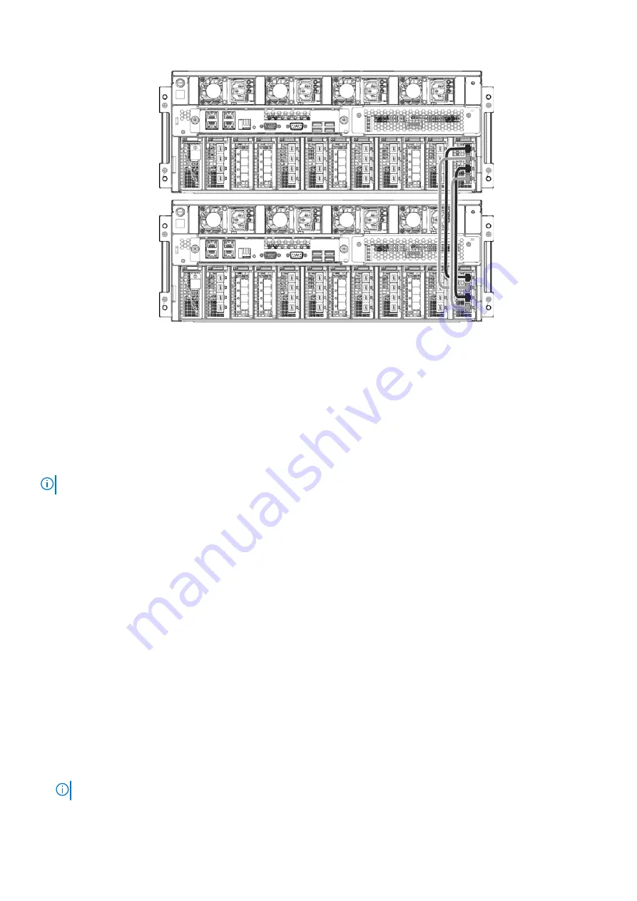
Figure 73. DD9500 HA interconnect
2. Cable port 0 of the interconnect I/O module in node 0, slot 11 to port 0 of the interconnect I/O module in node 1, slot 11.
3. Cable port 1 of the interconnect I/O module in node 0, slot 11 to port 1 of the interconnect I/O module in node 1, slot 11.
4. Cable port 2 of the interconnect I/O module in node 0, slot 11 to port 2 of the interconnect I/O module in node 1, slot 11.
5. Cable port 3 of the interconnect I/O module in node 0, slot 11 to port 3 of the interconnect I/O module in node 1, slot 11.
Connect data cables on both nodes
NOTE:
The data cabling for both nodes of the HA pair must be identical.
1. Enable data transfer Ethernet connectivity. Repeat for each connection.
a. If using 1 Gb copper Ethernet, attach a Cat 5e or Cat 6 copper Ethernet cable to an RJ-45 Ethernet network port (start
with ethMa and go up).
b. If using 10 Gb copper Ethernet with an SFP+ connector, use a qualified SFP+ copper cable.
c. If using 1/10 Gb fiber Ethernet, use MMF-850nm cables with LC duplex connectors.
d. For 10GBaseT connections, use Cat6a S-STP Ethernet cables.
2. Enable data transfer Fibre Channel (FC) connectivity. Repeat for each connection.
a. Attach a Fibre Channel fiber optical cable (LC connector) to an I/O module port on the controller, and attach the other
end (LC connector) to an FC switch or to an FC port on your server.
Power on the systems
Power the system on in the following order:
1. Expansion shelves
2. Active node
3. Standby node
Complete the following steps to power on the system:
1. Connect power cables to each expansion shelf receptacle and attach the retention clips.
2. Provide power to power on each expansion shelf. The shelves power on when plugged in. Ensure that each shelf power cable
is connected to a different power source.
NOTE:
Wait approximately 3 minutes after all expansion shelves are powered on before powering on the controller.
3. Provide power to power on the controller. Amber fault LEDs should turn on for all four power supplies.
Connect Cables and Power On
77
Содержание Data Domain DD9500
Страница 1: ...Dell EMC Data Domain DD9500 System Installation and Storage Expansion Guide November 2021 Rev 02 ...
Страница 65: ...Figure 66 DD9500 with ES30 shelves ERSO Connect Cables and Power On 65 ...
Страница 68: ...Figure 68 DD9500 with DS60 shelves DD9500 with HA For an HA DD9500 pair 68 Connect Cables and Power On ...
Страница 70: ...Figure 69 DD9500 with DS60 shelves HA 70 Connect Cables and Power On ...


