Deka unigy II SPACESAVER Non-Interlock AVR 45 AH Скачать руководство пользователя страница 5

4.  

Anchor holes can be marked and drilled with bases in place. 

Consult Appendix C for anchor hole pattern.  All anchor 

holes in base are required to be used to meet seismic re-

quirements. Consult local building codes for anchor  

bolt requirements. Anchor bolts not included due to site 

specific requirements.

5.  

Remove hardware holding modules together and holding 

modules to skid. Hardware removed from modules will 

be reused to attach modules to bases and to each other. 

Hardware holding modules to skid can be discarded.

6.   Module / Base Shimming
    a.   Prior to installation, the floor on which the battery 

string is to be installed should be level and capable of 

supporting the weight of the battery string. A 1° taper 

on a floor can result in a ½" variation at the top of one 

eight-high stack of modules. This can be compounded 

by the tolerance of each module.

    b.   Standard steel shim stock such as AISI/SAE 1010 can be 

used. Stainless steel is not required since these batteries 

are AGM and should not be exposed to a corrosive 

environment. Shim dimensions will vary depending on 

the location and levelness. Shims are not provided by 

East Penn due to site specific requirements.

    c.   If floors are not level, shim material can be placed under 

each of the base supports within a battery string until 

they are level. All base supports within a battery string 

must be level with each other – do not level individual 

bases as this could cause variation in height from one 

stack to another.

    d.   It is recommend to place an interstack connector on the 

system to ensure no stress will be placed on the cell 

posts. Reference Safety Section of this manual and  

battery schematic for all necessary precautions. If the 

connector is aligned, it may be removed and the module 

installation can continue.

    e.   Reference Appendix C for  

Base Support layout dimensions

    f.   Once all the modules are installed and aligned, joining 

plates (pg b.7 Part 3) which are provided with the parts 

kit should be installed at the top of every stack. This 

provides an additional tool to ensure levelness.

    g.   Assuming these guidelines are followed, the electrical 

connections can be installed easily without any issues  

of misalignment or undue stress on the cell posts.

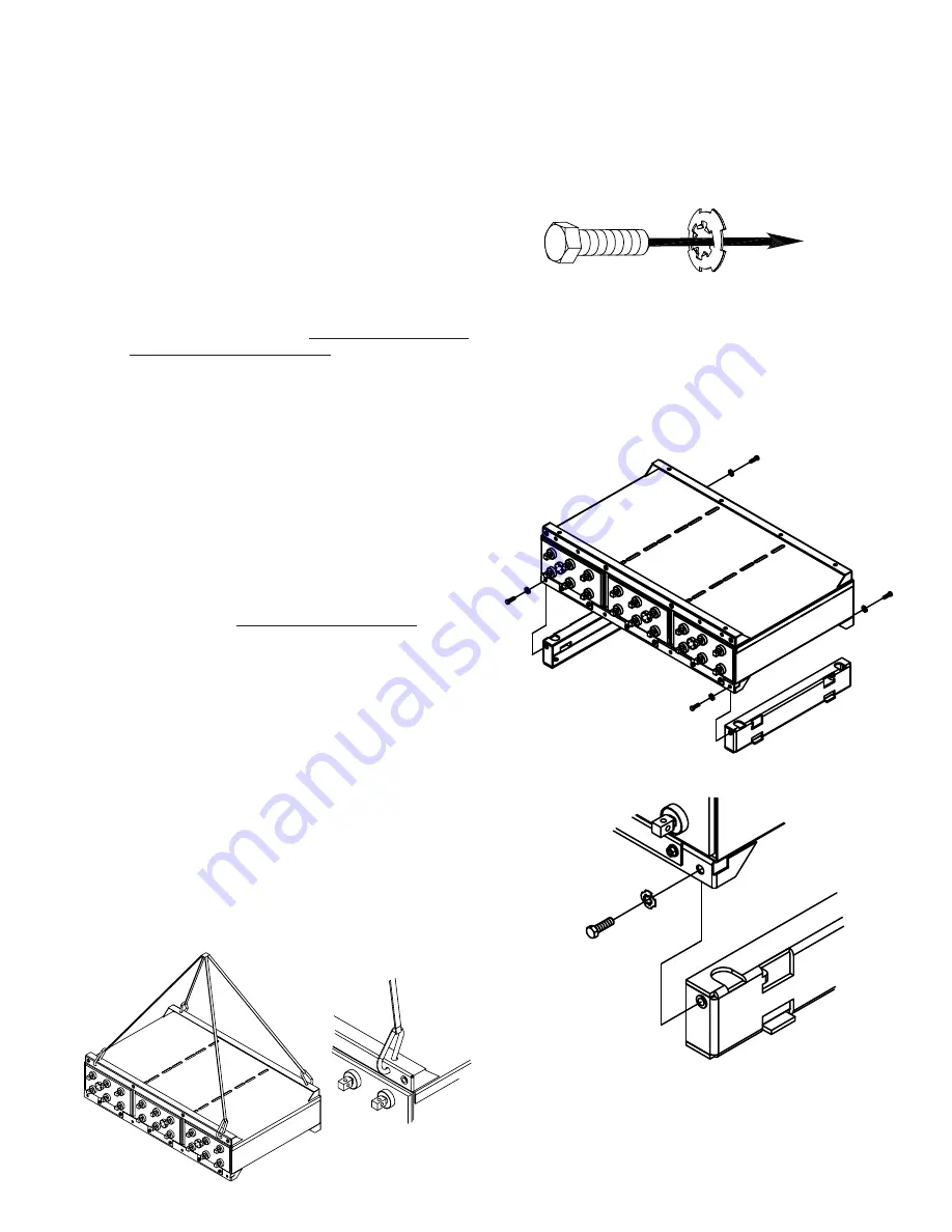
CAUTION: Never lift more than one module at a time with  

the supplied lifting slings.
7.   Install modules onto bases using supplied lifting straps. 

Two straps required to lift each module. Consult below  

diagram for proper sling attachment.

8.   Module connecting hardware is furnished with a dragon tooth 

washer in place of a lock washer and flat washer.  

The dragon tooth washer is used to enhance the electrical 

conductivity of the grounding system within a stack of 

modules. To ensure the dragon tooth washer is installed 

correctly; the curve of the washer must face away from the 

bolt head. Stack to stack grounding electrical conductivity  

is the responsibility of the installer.

b.5

9.   Installed battery string should be compared to battery string 

layout drawing for correctness. As each module is installed  

all hardware should be checked for proper torque before 

proceeding to next module.

   a.   Connecting the module to the base will require four 3/8-16 

x 1.25" bolts. One bolt for the front and one bolt for the 

rear required for each base. Consult “Hardware Torque 

Requirements” (pg b.4) for proper torque values.

    b.   Connect the modules to each other with eight 3/8-16 x 

1.25

"

 bolts & dragon tooth washers. Four for the front and 

four in the rear of each module. Procedure to be repeated 

until all modules are installed. Consult “Hardware Torque 

Requirements” (pg b.14) for proper torque values. 

Содержание unigy II SPACESAVER Non-Interlock AVR 45 AH

Страница 1: ...nd related accessories contain lead and lead compounds chemicals known to the State of California to cause cancer and reproductive harm Batteries also contain other chemicals known to the State of California to cause cancer WASH HANDS AFTER HANDLING E P M Form No 1112 Revised 12 21 2021 by EPM Printed in U S A ...

Страница 2: ...rmination b 14 Final Assembly Check Procedure b 18 Safety Shield Assembly b 18 Top Protection Shield Installation b 19 SYSTEM OPERATIONS Charge Voltage b 19 Charge Current b 19 Temperature Compensation b 19 Cell Voltage b 19 Rectifier Ripple Voltage b 19 RECORD KEEPING b 19 ACCEPTANCE TESTING b 20 MAINTENANCE Annual Inspection b 20 Battery Cleaning b 21 Capacity Testing b 21 Cell Removal Procedure...

Страница 3: ...tamper with the pressure relief valves except for cell replacement Warranty void if vent valve is removed 7 Inspect flooring and lifting equipment for functional adequacy 8 Adequately secure cell modules racks or cabinets to the floor 9 Connect support structures to ground system in accordance with applicable codes 10 The below IEEE Standards contain additional information Other standards may be r...

Страница 4: ...product Grounding When grounding the battery string proper techniques should be applied per electrical standards such as NEC and or local codes Two 0 201 diameter x 0 750 center holes are provided in back of each module to accept a 6 x 0 750 center compression grounding lug The holes must be tapped for a 1 4 20UNC thread and paint must be removed for a proper grounding pad location Note Battery st...

Страница 5: ...nnector is aligned it may be removed and the module installation can continue e Reference Appendix C for Base Support layout dimensions f Once all the modules are installed and aligned joining plates pg b 7 Part 3 which are provided with the parts kit should be installed at the top of every stack This provides an additional tool to ensure levelness g Assuming these guidelines are followed the elec...

Страница 6: ...nstalled at the outside corners of every 2 modules starting from the bottom and working towards the top This is to be repeated for each stack in the battery system For stacks containing odd number of modules an additional set of safety shield brackets will be required to be installed at the top of the module Use 3 8 16 x 2 50 hardware to install brackets Bracket should be flush with side of module...

Страница 7: ... Electrical Connection Connector Assembly 1 The contact surfaces of each individual post on every cell have been cleaned and coated with a thin film of No Ox ID A grease at the factory Assure the contact surfaces are free of dust or dirt prior to assembly 2 The battery string is supplied with a connector package appropriate to the required load the battery string is connected to Review the below c...

Страница 8: ...b 8 29 to 33 Plate 5 to 15 Plate 17 to 27 Plate ...

Страница 9: ...e will require 2 connectors per connection 1 per side see example below A 4CU package will require 4 connectors per connection 2 per side and a 6CU package will require 6 connectors per connection 3 per side Tighten torque all bolts after all connectors are installed Consult Hardware Torque Requirements pg b 4 for proper torque values b 9 1CU Package Detail 4CU Package Detail 6CU Package Detail 2C...

Страница 10: ...points Torque all hardware to 125 in lb 17 to 27 Plate 1 Install L connector with vertical bolt as below Bolt should be installed loosely for future adjustments Duplicate connection process at both connection points 3 Ensure proper alignment of connectors to cell posts 4 Tighten torque the horizontal bolt to 125 in lb prior to tightening and torqueing the vertical bolt in step 1 NOTE For this conn...

Страница 11: ...the module Use 3 8 16 x 1 25 hardware Install loosely for future alignment 29 to 33 Plate 1 Install L connector with vertical bolt as below Bolts should be installed loosely for future adjustments Duplicate connection process at both connection points 2 Install C connector to cell post using horizontal bolt as below Bolt should be installed loosely for future adjustments Duplicate connection proce...

Страница 12: ...uld be tightened but not torqued All remaining hardware should be torqued Consult Hardware Torque Requirements pg b 4 for proper torque values 4 Attach terminal plate to terminal plate bracket Note position of terminal plate Terminal plate bracket may have to be moved in order to be flush with the terminal plate 6 Assemble the four parts of the top terminal safety shield as detailed below b 12 ...

Страница 13: ... 2 hole lug Lug and lug hardware not included COMPLETED ASSEMBLY 5 to 15 Plate Assembly 21 to 27 Plate Assembly 17 to 19 Plate Assembly 125 33 Plate High Rate Assembly 29 to 33 Plate Assembly Top terminal plate hole to hole dimensions typical 21 to 33 top terminal plate detailed above 9 Lugs can be positioned on both sides of the terminal plate b 13 ...

Страница 14: ...r future adjustments Replace safety shield bracket at same location from previous step SLEEVE SPACER SLEEVE SPACER 4 Install side terminal connector to battery posts using 1 4 20 bolts Bolts should be installed loosely for future adjustments 3 The side terminal may be located at the bottom module Slot in lower arm of side terminal bracket slips over tab in base plate The upper side terminal bracke...

Страница 15: ...le connector 4CU 6CU CONNECTOR PACKAGE 1 4 20 x 1 25 hardware required 1CU 2CU CONNECTOR PACKAGE 1 4 20 x 1 00 hardware required 7 After all parts are installed and alignment is confirmed safety shield bracket hardware should be tightened but not torqued All remaining hardware should be torqued Consult Hardware Torque Requirements pg b 4 for proper torque values 8 Install side terminal shield to s...

Страница 16: ...l bracket attachment is different depending on the number of adjacent terminal plates TWO TERMINAL PLATE BRACKET ASSEMBLY FOUR TERMINAL PLATE BRACKET ASSEMBLY SIX TERMINAL PLATE BRACKET ASSEMBLY EIGHT TERMINAL PLATE BRACKET ASSEMBLY Installed in two sections SLEEVE SPACER SLEEVE SPACER SLEEVE SPACER SLEEVE SPACER SLEEVE SPACER SLEEVE SPACER ...

Страница 17: ...esigned to use up to 0 50 dia bolt and a maximum 1 75 centers 2 hole lug Plate is capable of handling 4 runs of cable Lugs can be positioned on both sides of the terminal plate Lug and lug hardware not included Lug Positioning Options ...

Страница 18: ...r than 10 of the average of all the same type connections i e intercell intermodule etc 4 Battery string performance is based on the output at the cell terminals Therefore the shortest electrical connection between the battery string and the operating equipment results in maximum total system performance Select cable size based on current carrying capability and voltage drop Cable size should not ...

Страница 19: ...every 13 F 7 C increase in operating temperature above 77 F 25 C the warranty period will be proportionally reduced by 50 as shown below The battery string operating temperature should not exceed 95 F 35 C and should never exceed 105 F 40 5 C for more than an eight hour period If operating temperatures are ex pected to be in excess of 95 F 35 C contact East Penn for recommendations Discharging at ...

Страница 20: ...ll times Review Safety Precautions on pg b 3 Annual Inspection For Renewable Energy Cyclic applications some of the following recommendations may not apply Discharge and recharge affect voltage and ohmic values These readings should be taken only after the battery string has been on continuous uninterrupted float charge for at least one month The following values should be recorded using the Batte...

Страница 21: ...t excessive voltage drop and or excessive temperature rise Should it be determined that any individual cell s need to be replaced contact East Penn CELL REMOVAL PROCEDURE 1 Before removing cell review Safety Precautions pg b 3 of this manual Contact East Penn with specific questions or concerns 2 Disconnect Charger and the system ground connection 3 Remove connectors from cell being removed 4 Remo...

Страница 22: ...re 1 Cells develop internal pressure Relieving this pressure from the cell will make it easier to install the cell into the module Follow the steps of Cell Removal Procedure item 4 2 Ensure cell polarity is correct prior to installing cell 3 Replace cell retainer bar 4 Refer to Electrical Connection section for installing connectors of replacement cell ...

Страница 23: ... 6 Cells 7 Cells 8 Cells 9 Cells 10 Cells 11 Cells 12 Cells 13 Cells 14 Cells 15 Cells 16 Cells 17 Cells 18 Cells 19 Cells 20 Cells 21 Cells 22 Cells 23 Cells 24 ALL FIELDS TO THE RIGHT OF THE CELL NUMBER ABOVE MUST BE COMPLETED EPM ORDER NUMBER WILL APPEAR ON THE SHIPPING LABEL ON THE CARTON COVERING EACH PALLET OF CELLS TO ENSURE CONTINUATION OF WARRANTY SUBMIT FORMS TO East Penn Mfg Co Inc Rese...

Страница 24: ...90 2 68 AVR75 13 72 33 1 61 6 09 17 44 7 91 6 97 3 16 AVR75 15 83 38 1 86 7 03 20 13 9 13 8 05 3 65 AVR75 17 94 43 2 10 7 96 22 81 10 35 9 12 4 14 AVR75 19 105 48 2 31 8 75 25 08 11 38 10 02 4 55 AVR75 21 116 53 2 60 9 84 28 19 12 79 11 27 5 11 AVR75 23 127 58 2 84 10 77 30 87 14 00 12 34 5 60 AVR75 25 137 62 3 09 11 71 33 56 15 22 13 42 6 09 AVR75 27 148 67 3 34 12 64 36 23 16 44 14 48 6 57 AVR75...

Страница 25: ...b 25 APPENDIX C Non Interlock Base Anchor Hole Pattern ...

Страница 26: ... 51 8 10 2 280 2 430 50 Cell Type Max Charge Current A Min Charge Current A AVR45 5 16 5 4 9 AVR45 7 24 7 7 4 AVR45 9 32 9 9 9 AVR45 11 41 1 12 3 AVR45 13 49 4 14 8 AVR45 15 57 6 17 3 AVR45 17 65 8 19 7 AVR45 19 74 1 22 2 AVR45 21 82 3 24 7 AVR45 23 90 5 27 2 AVR45 25 98 7 29 6 AVR45 27 107 32 1 AVR45 29 115 34 6 AVR45 31 123 37 0 AVR45 33 132 39 5 Cell Type Max Charge Current A Min Charge Current...

Страница 27: ... 412 2 262 2 442 69 8 20 2 415 2 265 2 445 68 0 19 2 418 2 268 2 448 66 2 18 2 421 2 271 2 451 64 4 17 2 424 2 274 2 454 62 6 16 2 427 2 277 2 457 60 8 15 2 430 2 280 2 460 59 0 14 2 433 2 283 2 463 57 2 13 2 436 2 286 2 466 55 4 12 2 439 2 289 2 469 53 6 11 2 442 2 292 2 472 51 8 10 2 445 2 295 2 475 50 3mV per ºC Renewable Energy Cyclic Voltage Compensation Renewable Energy Cyclic Charge Paramet...

Страница 28: ...5 29 150 AVR45 31 161 AVR45 33 172 AVR95 Series Cell Type Max Charge Current A AVR95 7 67 8 AVR95 9 90 4 AVR95 11 113 AVR95 13 136 AVR95 15 158 AVR95 17 181 AVR95 19 203 AVR95 21 226 AVR95 23 248 AVR95 25 271 AVR95 27 294 AVR95 29 316 AVR95 31 339 AVR95 33 361 Cell Type Max Charge Current A AVR75 5 35 5 AVR75 7 53 2 AVR75 9 70 9 AVR75 11 88 7 AVR75 13 106 AVR75 15 124 AVR75 17 142 AVR75 19 160 AVR...

Страница 29: ...___________________________________________ mfg model Rectifier Mfg Model__________________________________________________ AC Ripple Voltage _______________________ Note if voltage is expressed in RMS Peak or Peak To Peak Environment i e Hut Central Office etc ___________________________________________________________________________________________________________ Consult Cell type Battery Type...

Страница 30: ...__________________________ Cell Serial Cell Volts Cell Connector Ohmic Value Cell Serial Cell Volts Cell Connector Ohmic Value No Number Temp Float Ohmic Value 1 2 3 No Number Temp Float Ohmic Value 1 2 3 61 111 62 112 63 113 64 114 65 115 66 116 67 117 68 118 69 119 70 120 71 121 72 122 73 123 74 124 75 125 76 126 77 127 78 128 79 129 80 130 81 131 82 132 83 133 84 134 85 135 86 136 87 137 88 138...

Страница 31: ...6 197 237 198 238 199 239 200 240 Battery Maintenance Report Company_______________________________________________________________________ Service Date________________________________________________ Address_______________________________________________________________________ Battery Dwg ________________________________________________ Battery Location I D Number_ _ ____________________________...

Страница 32: ... www dekabatteries com E P M Form No 1112 12 21 2021 by EPM Printed in U S A All data subject to change without notice No part of this document may be copied or repro duced electronically or mechanically without written permission from the company e mail reservepowersales dekabatteries com ...

Отзывы: