background image

Ulyxe PL

TM


38 


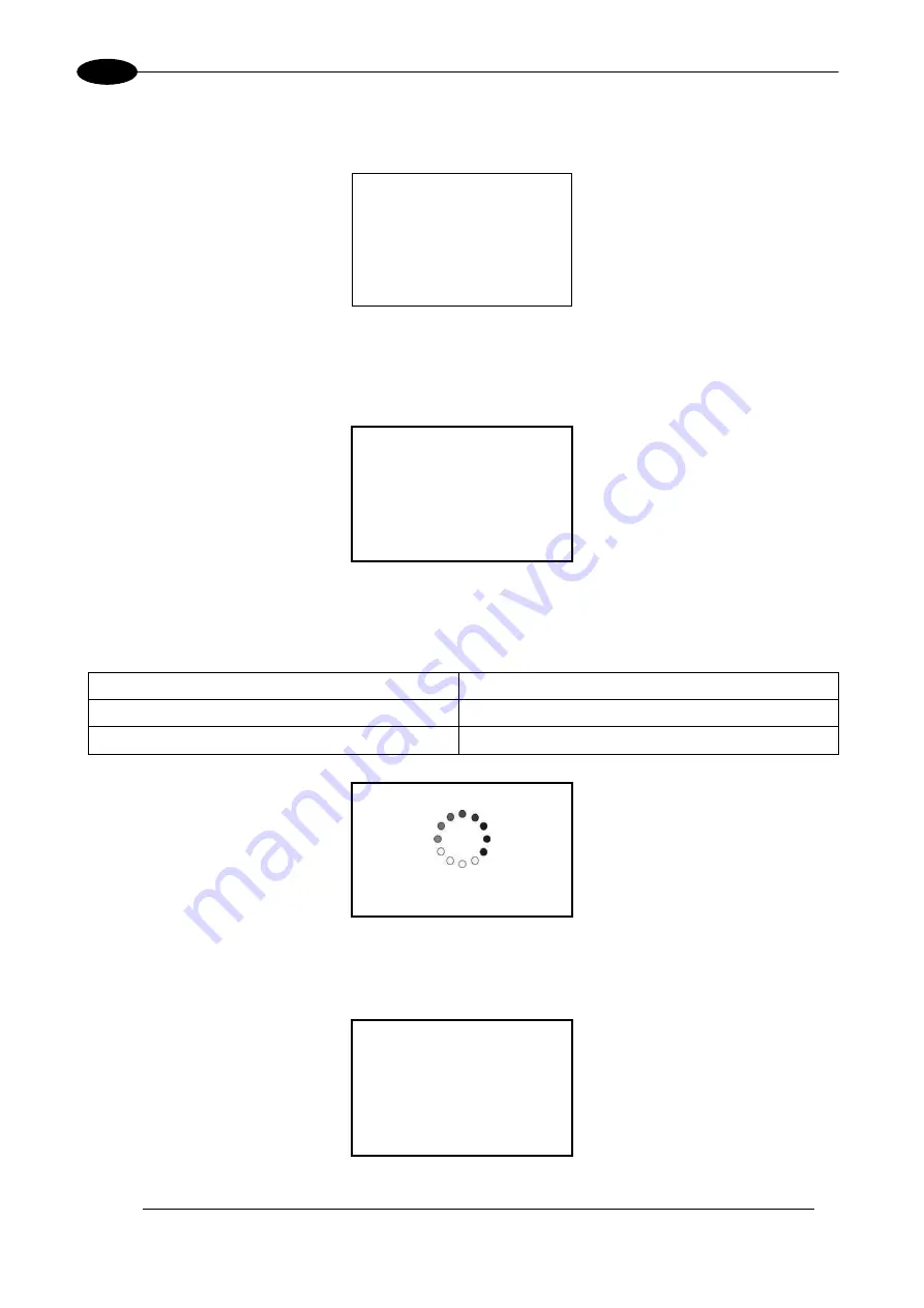
The fans cooling system will be powered on and it will be showed LCD firmware version on remote display 
temporarily (if present), then LED bar will be lighted on in orange colour until system power on time will be 
not completed: 

REMOTE CAN 

LCD 


STARTING SYSTEM 

Please Wait 

Figure 27: Starting system. 

Immediately after LED bar is lighted off Ulyxe PL™ remains in waiting for key start mode and power module 
is off: 

REMOTE CAN 

LCD 


WAITING FOR START 

[turn on the key] 

Figure 28: Waiting for key start. 

2

N

 step:


activate 

“KEY”

 signal to start Ulyxe PL™ and wait for system warm up. During this operation LED 

bar will come green blinking. 

SIGNAL 

STATUS 

KEY 

ON 

SHUTTER EN 

OFF 


WARM UP 


PLEASE WAIT 

Figure 29: Waiting for warm up. 

Once warm up is completed the LED bar comes steady green and the marking system is ready to use: 

REMOTE 

CAN 

LCD


Figure 30: Ulyxe PL™ waiting ENABLE command. 

Содержание Ulyxe PL

Страница 1: ...USER S MANUAL Ulyxe PLTM ...

Страница 2: ...n of Datalogic S p A and or its affiliates Datalogic and the Datalogic logo are registered trademarks of Datalogic S p A in many countries including the U S A and the E U Ulyxe Ulyxe PL Lighter Suite are trademarks of Datalogic S p A and or affiliates All other trademarks and brands are property of their respective owners Datalogic reserves the right to make modifications and improvements without ...

Страница 3: ...nough to constitute an electrical risk This symbol may also appear on the marking system at the risk area Laser Warning This symbol indicates the danger of exposure to visible or invisible laser radiation This symbol may also appear on the marking system at the risk area Fire Warning This symbol indicates the danger of a fire when processing flammable materials Because there is a danger of fire it...

Страница 4: ...ows 7 compatibility 821002090 rev A 02 05 2012 Power supply plug and connector Prerequisites for installation 821002091 rev B 20 06 2012 General Review 821002092 rev C 10 04 2014 12 23 48 49 Appendix E 821002093 rev D 13 06 2016 General Review 821002094 rev E 06 06 2017 ii NOTE We sometimes update the documentation after original publication Therefore you should also review the documentation on ww...

Страница 5: ...ad the section of the manual concerning safety instructions as well as the sections related to matters falling under her his responsibility The workers assigned to the marking system can be identified as OPERATOR responsible for loading elements to be processed visually checking the work cycle removing the finished product and cleaning the marking system MAINTENANCE PERSONNEL responsible for the e...

Страница 6: ...in the laser world without compromises about performance and to obtain excellent markings Ulyxe PL TM system includes all necessary to operate a laser source DPSS Q switched a galvanometer scanning head digital power controls cooling system and monitoring functions The entire unit and its mechanical base are covered with a metal casing that makes it more resistant to external agents The user can e...

Страница 7: ...nes any and all responsibility for work carried out on live parts by untrained or unauthorized personnel WARNING It s not allowed modify destination use of the marking system in different way of its functions Datalogic declines any responsibility and liability for irregular and improper use of the marking system which it manufactures WARNING These marking system actuation is demanded to the system...

Страница 8: ...IGH SPEED or quality USB2 0 cable not longer than 2 meters Avoid using any kind of extension cable or any HUB on the cable path Verify the compatibility of the operative system Some computers support only one USB2 0 at a time On those systems the use of other devices USB memories external HD etc can disconnect the Ulyxe PL peripheral devices in particular it is observed that any USB 2 0 peripheral...

Страница 9: ...IPTION OF THE LASER MODULES 18 2 3 MARKING AREA SPECIFICATION 19 2 4 CONNECTORS SPECIFICATIONS 21 2 4 1 AUX INTERLOCK CONNECTOR SW LEVEL 21 2 4 2 CONTROL BOX CONNECTOR LASER CONTROL 22 2 4 3 POWER SUPPLY CONNECTOR 24 2 4 4 POWER SUPPLY CABLE 24 2 4 5 RS232 CONNECTOR 24 2 5 INPUT OUTPUT SIGNAL SPECIFICATIONS 25 2 6 CONNECTION EXAMPLE 26 3 INSTALLATION AND SET UP 28 3 1 LIGHTER SUITE INSTALLATION 28...

Страница 10: ...S 57 CE COMPLIANCE 57 FCC COMPLIANCE 57 APPENDIX C NOTE ABOUT LASER 58 LASER SAFETY 58 LASER RADIATION 59 ABSORPTION OF LASER RADIATION 60 CLASSIFICATION AND DANGER LEVEL 60 RADIATION VIEWING CONDITIONS 61 DIRECT VIEWING OF THE LASER BEAM 61 DIRECT VIEWING OF THE BEAM AFTER MIRROR REFLECTION 61 DIRECT VIEWING OF THE BEAM OUTPUT BY AN OPTICAL FIBER 61 DIRECT VIEWING OF THE BEAM AFTER FOCUSING 61 SC...

Страница 11: ...both hands Figure 2 Unpacking Before installing or operating the marking system you should Inspect the shipping container for damage Inspect the marking system for signs of damage Confirm that the shipping carton contains all items on the shipping inventory list including any accessories Retain all packaging materials until the marking system has been inspected for completeness and damage and you ...

Страница 12: ...1PWX T0SV 1 3 CABLE AND ACCESSORIES Power supply cable USB cable RS232 cable Aux Interlock connector gold USB key Control Box connector User Manual Test Report Sample Test If this connector is used the marking system works in DANGEROUS condition MUTING DEVICE ...

Страница 13: ... moisture condensation may cause a malfunction of the marking system If moisture condensation occurs Turn off the marking system and wait about 1 hour for the moisture to evaporate Note on moisture condensation Moisture may condense when you bring the marking system from a cold place into a warm place or vice versa or when you use the marking system in a humid place as shown below How to avoid moi...

Страница 14: ...e threaded holes and fixing pins drivers WARNING It is very important to secure the marking system before you start marking the piece since improper securing or positioning may cause serious damage Do not secure the marking system in a way other than the one described in the figure NOTE In order to prevent marking distortions check for the absence of vibrations between marking system and piece to ...

Страница 15: ...l a heat source near Figure 6 Installation environment To obtain a good marking quality and not to decrease life time we recommended a ventilation or vacuum system in a protection box to limit dust due to marking phase 1 8 FUME DUST EXTRACTOR During marking process dust and or gas may be produced It is important to use adequate fume extractor and or air filtration WARNING Marking PVC or other plas...

Страница 16: ... PRODUCT and it is the responsibility of the OEM system integrator to provide the safety completeness to be ready to use 2 1 TECHNICAL SPECIFICATION MECHANICAL CHARACTERISTICS Weight 7 8 Kg Height 123 5 mm Width 145 6 mm Depth 410 mm IP Rating 21 without F Theta scan lens in horizontal position only NOTE Refer to Datalogic s website for detailed drawings ...

Страница 17: ...AL POWER SUPPLY Input Voltage 24V DC Input Current 13 A max Max Power 300 W PERFORMANCE LASER MARKER SOURCE typical values 25 C Laser Type Class 4 DPSSL Diode Pumped Solid State Laser Average Power reference Rep Rate 50kHz 1 W 6 5 Pulse energy max reference Rep Rate 15kHz mJ 0 30 Central emission wavelength nm 1064 Repetition Rate kHz 15 200 Laser aiming beam Class 2 1mW 630 670nm Focus aiming bea...

Страница 18: ... the marking system is provided here below Figure 7 Marking system view 1 Status LED bar 7 Control Box connector 2 LED indicators 8 Aux Interlock connector 3 Main Switch with LED 9 USB port type B 4 Power supply connector 10 F Theta Scan Lens 5 CAN connector 11 Focusing beam 6 RS232 port ...

Страница 19: ...NOTE Definition of Marking Area square marking field measured on black anodized aluminium plate WARNING This product was designed to use only certain configurations of F Theta lens and marking field If your needs are not satisfied by current available F Theta lens configurations please contact Datalogic for a solution The use of other F Theta lenses or operation outside the specified marking field...

Страница 20: ...and the last mechanical edge of the F Theta Scan Lens Refer to the following figure WD Working Distance FD Fixing Distance MA Marking Area AB Aiming beam FB Focusing beam Figure 8 Marking area NOTE For systems equipped with standard F Theta Scan Lens the focus condition is obtained by matching the Aiming Beam with the Focusing beam ...

Страница 21: ...RIPTION FUNCTIONAL DIAGRAM 1 VCC OUTPUT 5V DC for INTERLOCK signal 2 INTERLOCK INPUT INTERLOCK signal 3 GND GROUND DO NOT CONNECT 4 N C NOT USED PLUG CONNECTOR Connector type BINDER 719 series 4 positions Figure 10 Male plug connector cod 09 9767 00 04 front view WARNING If the Aux interlock gold connector is used the marking system is in DANGEROUS condition MUTING DEVICE NOTE To restore the marki...

Страница 22: ...MODE SW_READY COMPATIBILITY true ON when a document or a sequence is running in AUTO MODE and laser in READY state SW_READY COMPATIBILITY false ON when a script is running n AUTO MODE and IoPort setReady true function is used 7 BUSY Digital Output This signal is used to know if the current spooler is executing marking in progress see paragraph 2 4 2 2 ON during marking process 8 END Digital Output...

Страница 23: ...ntervals in the diagram can all be programmed by a resolution of 1 ms T1 Start Time For setting the minimum acceptable time for the start marking signal T2 Start Delay For delaying marking start T3 Busy Advance BUSY signal corresponding to mark progress T4 Stop Time The minimum time for STOP signal to stop the marking process T5 Busy Delay For delaying the Laser END signal with respect to laser em...

Страница 24: ...ce Power supply input reference C FG Earth Earth connection D N C NOT USED 2 4 4 POWER SUPPLY CABLE Male plug connector SOURIAU TRIM TRIO 4 ways cod UT0610 4PH 3 meter length Figure 15 Male plug connector cod UT0610 4PH front view and wiring 2 4 5 RS232 CONNECTOR Connector type BINDER 768 series 3 positions Figure 16 Female panel socket cod 99 3412 281 03 front view PIN SIGNAL TYPE DESCRIPTION 1 T...

Страница 25: ...1 mA 5 V DC Pulse Width 1ms debounce MIN TYP MAX INPUT Logic LOW 0 0 V DC 0 0 V DC 1 0 V DC INPUT Logic HIGH 3 5 V DC 5 0 V DC 7 0 V DC DIGITAL OUTPUT Type Darlington open collector low side Vmax 50 V DC Imax 150 mA Vsaturation 0 5 V DC Leakage current 5 µA OUTPUT State ON V 0 3 V DC I 150mA OUTPUT State OFF V 5 0 V DC I 5µA ...

Страница 26: ...7 Connection example WARNING It is important to install an emergency circuit able to cut 24V DC power supply voltage or indirectly on 110 220V AC switching off Ulyxe PL entirely This safety circuit needs to be installed from qualified personnel only ...

Страница 27: ...TECHNICAL SPECIFICATIONS 27 2 EXAMPLE OF CONNECTION TO PLC Figure 18 Example of connection to PLC ...

Страница 28: ...b of free space on hard disk 32 bit or 2 GB 64 bit Graphic card Minimal resolution 800 x 600 1280 x 1024 recommended USB USB 2 0 Furthers RS232 serial port WARNING Connect Ulyxe PL to PC through USB cable only after Lighter Suite software installation DO NOT CONNECT USB cable until it is not required from installer NOTE Ulyxe PL works only and exclusively with USB 2 0 Full Speed device connections...

Страница 29: ...INSTALLATION AND SET UP 29 3 3 Wait while Setup is loading 4 Press Next to continue 5 Press I Agree to accept licence agreement ...

Страница 30: ...Ulyxe PLTM 30 3 6 Select INTERACTIVE installation type press Next to continue 7 Select the components to install and press Next to continue ...

Страница 31: ...INSTALLATION AND SET UP 31 3 8 Choose the destination folder and press Install to continue 9 Provide laser configuration file located on USB pen drive supplied with equipment and press Open to continue ...

Страница 32: ...Ulyxe PLTM 32 3 10 Microsoft Windows will ask you to install the device driver press Install to continue 11 Wait while Lighter Suite is installing 12 Press Finish to complete the installation ...

Страница 33: ...NG Connect Ulyxe PL to PC through USB cable only after Lighter Suite software installation 3 2 1 CONTROL BOX CONNECTOR CONNECTION Figure 19 Connecting Control Box connector NOTE The Control Box connector must always be inserted and wired properly in order to use the marking system If this connection is not present the marking system goes in error status In option it is possible to use Control Box ...

Страница 34: ...ystem The absence of such connector locks the marking system 3 2 3 POWER SUPPLY CABLE CONNECTION Connect power supply cable to Ulyxe PL Check connector right orientation and plug in Once plugged in check also right coupling between two connectors parts Figure 21 Power Supply cable plug in WARNING Ulyxe PL needs a safety circuit for emergency Consult chapter 2 6 for more details WARNING Ulyxe PL ne...

Страница 35: ...ter Lighter Suite software installation Plug USB cable first on Ulyxe PL device side Figure 22 Plug USB system side Plug USB cable to PC side Figure 23 Plug USB PC side Wait while Microsoft Windows is installing device drivers A message in the Laser Engine tray icon will advise you that Ulyxe PL is plugged in ...

Страница 36: ... THETA LENS PROTECTION CAP REMOVAL Remove the F Theta Lens protection cap before marking operation Figure 24 F Theta Lens protection cap removal WARNING Marking with the lens protection cap could result in damage to the lens ...

Страница 37: ... connector and USB cable as described in the previous chapter SIGNAL STATUS KEY OFF SHUTTER EN OFF 1 ST step turn on the main switch in the back of the marking system Figure 25 Power on If power supply input is correct green LED indicator on back panel will light on otherwise if there is a reversed voltage input red LED indicator on back panel will light on Refer to troubleshooting paragraph in ca...

Страница 38: ... is lighted off Ulyxe PL remains in waiting for key start mode and power module is off REMOTE CAN LCD WAITING FOR START turn on the key Figure 28 Waiting for key start 2 N step activate KEY signal to start Ulyxe PL and wait for system warm up During this operation LED bar will come green blinking SIGNAL STATUS KEY ON SHUTTER EN OFF WARM UP PLEASE WAIT Figure 29 Waiting for warm up Once warm up is ...

Страница 39: ...for operation See chapter 5 3 for Touch Screen display functions NOTE For information about use of Lighter software see related manual 3 TH step activate SHUTTER EN command to open mechanical shutter LED bar comes steady orange ALARM signal will be active and yellow LED indicator on back panel will light on SIGNAL STATUS KEY ON SHUTTER EN ON Figure 32 Orange LED Bar stand by system ...

Страница 40: ...m is READY to mark NOTE If aiming and focusing beam laser diodes setup are in automatic mode they ll be light off If marking operation starts LED bar comes steady red and on remote display will be showed laser emission status Figure 34 Laser emission Figure 35 Red LED bar laser emission ...

Страница 41: ... and to show system status Figure 36 Control Box Ordering no 985330001 1 I O connection Connection to Ulyxe Control Box connector 2 SHUTTER ENABLE Selector switch with LED indicator to open shutter 3 ALARM LED indicator LED indicator for system in READY state 4 START marking BUSY LED indicator START marking command pushbutton with BUSY LED indicator 5 STOP marking END LED indicator STOP marking co...

Страница 42: ... Ripple Noise 150mV Input voltage 85 265 V AC 47 63Hz Size 61 x 82 x 165 mm Withstand Voltage Input to ground 2 5kV AC Input to Output 3kV AV Output to ground 500V AC Isolation voltage 100MΩ Output to ground 500V DC Mark CE Mark EMI compliance EN55011 EN55022 FCC VCCI Class B Immunity compliance IEC61000 4 2 3 4 5 6 Level 3 8 Level 4 11 Safety Agency Approvals UL60950 1 CSA60950 1 EN60950 1 EN5017...

Страница 43: ...erative parameters error messages and to setup aiming beam and focusing beam diodes functionality It is comprehensive of Touch Screen display connection cable for Ulyxe PL with 2 mt length and a metal cover with fixing elements Figure 39 Remote CAN display and cable Figure 40 Remote CAN display overall dimensions Selection areas Touch Screen Figure 41 Selection areas Touch Screen ...

Страница 44: ...TO ON OFF AUTO WAITING FOR START turn on the key WARM UP Please wait System OFF System warm up System standby ready Pushing touch screen SYSTEM MONITOR menu selection STAND BY SERVICE LASER MONITOR SERVICE SYSTEM LASER M menu selection menu selection STAND BY STAND BY menu selection STAND BY menu selection STAND BY menu selection STAND BY Status system Language English STAND BY STAND BY STAND BY S...

Страница 45: ...rn to the main screen with the REMOTE CAN LCD logo Press the bottom right arrow to access the next selection menu Lc Te La STAND BY Data contained in the SERVICE menu LcdFW FW version of the LCD card TecFW FW version of the power mainboard Language language is set on English Press the bottom left arrow to return to the main screen with the REMOTE CAN LCD logo B In H STAND BY S Information containe...

Страница 46: ... with the REMOTE CAN LCD logo AIMIN menu STAND BY Selection menu to set the aiming laser diode Press the middle area to select it and display the settings Press the bottom left arrow to return to the main screen with the REMOTE CAN LCD logo Press the bottom right arrow to switch to the focusing diode ON STAND BY mode Sa Selection menu to set the red diode Press the bottom left arrow to confirm the...

Страница 47: ...ll not be held liable for any non conforming use of marking system of its manufacture It is forbidden to operate the marking system before the machine it is intended for has been declared in conformance with statutory Directives WARNING Access to the internal parts of the marking system is only permitted for authorized personnel who have been trained and instructed on the electrical risks Datalogi...

Страница 48: ...have to be controlled MAINTENANCE PROGRAM COMPONENT OR FUNCTION TYPE OF OPERATION INTERVALS F Theta Scan Lens Check Clean Weekly wipe gently with a dry cloth or soaked in high purity isopropyl alcohol or clean it with air blowing Fan and heat exchanger unit Check Every 3 months according to the environment and frequency of use 6 2 1 F THETA SCAN LENS CLEANING PROCEDURE Figure 43 Cleaning laser out...

Страница 49: ...ser diode MAX voltage 2 5V 3 5V Peltier module MAX current 12A 15A MIN input voltage 22 5V 6 3 1 LIST OF POSSIBLE MALFUNCTIONS STATUS CAUSE ACTION Red LED bar blinking An internal error has occurred and the system is in software protection mode Check the error message shown on the display and refer to paragraph 6 3 2 for the recovery procedures Orange LED bar blinking Warning status The display sh...

Страница 50: ...tc Cut off power supply to the Ulyxe PL externally and wait 30 60 minutes before restarting Contact technical assistance if the problem persists The USB connection is not working No connection between PC and Ulyxe PL Make sure the right Ulyxe PL USB driver as well as the connection cable are present Please refer to section USB 2 0 ADVICE for additional info The LCD does not work No power on the di...

Страница 51: ...ns off the entire power section laser diode Peltier module RF driver etc since the laser diode temperature controller is out of control Turn off wait 30 60 minutes and restart Make sure the room temperature complies with the specifications Read the value displayed in the Diode Temp field in the LASER MONITOR section and checks to see if it deviates from the Set point value In case the problem reoc...

Страница 52: ...In case the problem re occurs carry out the data log with the service tool and contact technical assistance S HEAT SINK HIGH TEM FAULT The temperature software level on the central heat sink was exceeded The value is set at 60 C The system turns off the entire power section laser diode Peltier module RF driver etc since the internal heat cannot be dissipated The problem may be caused by critical e...

Страница 53: ...ff the entire power section laser diode Peltier module RF driver etc since the system may emit an unwanted laser beam The problem may be caused by a malfunction of the shutter or of its position sensor or the internal card may be malfunctioning Turn off wait 30 60 minutes and restart In case the problem re occurs carry out the data log with the service tool and contact technical assistance DISABLE...

Страница 54: ...inal packing and include all original accessories and documentation as detailed in the original inventory It is advised that the correct and original packaging is used to prevent transit damage to the marking system If part or all of the original packaging is unavailable please contact Datalogic for replacement items Please take time to complete all return documentation This can be obtained from D...

Страница 55: ... labels 3 Label for panels Aperture label USB plug I O Power ON switch RS232 Serial communication CAN CanBus communication CONTROL BOX Control Box connector AUX INTERLOCK Interlock connector 3 Maximum output of laser radiation as per definition 3 55 of IEC60825 1 considering single fault conditions ...

Страница 56: ...56 LABELS LOCATION Figure 44 External labels location ...

Страница 57: ...clude an adequate analysis and assessment of the risk s This evaluation was carried out in relation to the applicable points of the standards listed in the Declaration of Conformity Datalogic products are mainly designed for integration purposes into more complex systems For this reason it is under the responsibility of the system integrator to do a new risk assessment regarding the final installa...

Страница 58: ...ING BEFORE INSTALLING AND USING THE MARKING SYSTEM READ CAREFULLY THE APPENDIX CONCERNING LASER SAFETY WARNING The marking system is a Class 4 laser product Visible and invisible laser radiation can be diffused Avoid skin exposure to direct or reflected radiation WARNING Direct vision of a laser beam may cause irreversible damage to eyes WARNING Wear protection glasses while using the marking syst...

Страница 59: ... intense with the result that it can be very harmful to the eye and present vision problems WARNING Directly viewing a Laser beam can cause irreversible damage to vision To prevent permanent damage to vision a few precautions must be taken All individuals who may be exposed to dangerous levels of laser radiation must know that the laser is active and wear protective goggles if necessary Due to its...

Страница 60: ...of the crystalline lens melanic coloring or reddening of the skin Greater wavelengths infrared IR A 780 1400 nm IR B 1400 3000 nm IR C 3000 10 E6 nm generally cause thermal effects detachment or photocoagulation of the retina burning of the skin The degree of injury obviously depends on the amount of absorbed radiation and the instantaneous power of the radiation source CLASSIFICATION AND DANGER L...

Страница 61: ...CT VIEWING OF THE BEAM AFTER MIRROR REFLECTION This may occur by directing the beam on a reflecting surface Viewing of a mirror reflected beam from a flat surface is very dangerous and equal to direct viewing DIRECT VIEWING OF THE BEAM OUTPUT BY AN OPTICAL FIBER This happens if an Optical Fiber disconnects from the resonator Viewing of the beam is dangerous up to a significant distance Filters and...

Страница 62: ...sk and of the optical density requested to the protection filters of the laser radiation Calculations have been done following the CEI EN 60825 1 2014 Normative regarding Nominal Ocular Hazard Distance N O H D in the worst condition and in case of accident exposition of 10 seconds per direct radiation and 100 seconds for diffused radiation Laser type Nd YVO4 1064 nm Application type Marking Emissi...

Страница 63: ...ng to use a reduction power of 50 and a total accidental reflection for a 10 seconds maximum The protection goggles must have such an optical density to bear down the radiation under the maximum permitted value previously calculated according to the here below reported calculation O D 5 3 1064 nm D I R SCALE INDEX OF THE PROTECTION GOGGLES FILTER The scale index L of the filters indicates the stab...

Страница 64: ...serve as a reference for the Operator and shall be written in his her language Training is essential and must include Familiarization with system operating procedures Knowledge of the biological effects of radiation on the Eyes and Skin Understanding of the necessity for Individual Protection Devices I P D COLLATERAL RISKS If the intended use of the source is changed for example for material proce...

Страница 65: ...or example during the intended use of the Laser source if a material being processed undergoes alterations and produces irritating and or toxic fumes it may be necessary to remove the fumes from processing before releasing them into the air An additional risk may be represented by fire caused by processing materials other than those the equipment was designed for WARNING Do not subject materials o...

Страница 66: ...66 APPENDIX D MECHANICAL DRAWINGS NOTE Please refer to Datalogic website for detailed drawings ...

Страница 67: ...0 Connecting Aux interlock connector 34 Figure 21 Power Supply cable plug in 34 Figure 22 Plug USB system side 35 Figure 23 Plug USB PC side 35 Figure 24 F Theta Lens protection cap removal 36 Figure 25 Power on 37 Figure 26 Green and red LED on back panel 37 Figure 27 Starting system 38 Figure 28 Waiting for key start 38 Figure 29 Waiting for warm up 38 Figure 30 Ulyxe PL waiting ENABLE command 3...

Страница 68: ...68 ...

Отзывы: