i50 Manual (5.51)
Page 72
© 2018 Datalink Systems, Inc.
www.datalinksystemsinc.com
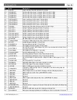
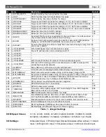
ID
Name
Description
Default
181
I_OUTPOLARITY4
Output 4 polarity. See note at bottom for values
1
182
I_VOUT
VOUT function. See I/O note at bottom for values
40
183
I_VOUTPOLARITY
VOUT polarity. See note at bottom for values
1
184
I_ADC1HIGH
Trigger event if ADC1 exceeds this voltage (1/10 V). Set to zero to disable
0
185
I_ADC1LOW
Trigger event if ADC1 drops under this voltage (1/10 V). Set to zero to disable 0
186
I_ADC2HIGH
Trigger event if ADC2 exceeds this voltage (1/10 V). Set to zero to disable
0
187
I_ADC2LOW
Trigger event if ADC2 drops under this voltage (1/10 V). Set to zero to disable 0
188
I_DEBOUNCEADC1
Debounce time (ms) for ADC1 changes
100
189
I_DEBOUNCEADC2
Debounce time (ms) for ADC2 changes
100
190
I_NOGPS
Send alert if GPS signal is unavailable for this period (sec). Ver 4.88 and later
only increment this counter while vehicle is moving.
0
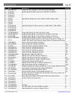
191
I_RXUNIT
Kenwood unit number used to listen for data from base radio (1000-4999 for
Fleetsync, or 00001-65519 for NXDN). Set to zero to use I_UNIT
0
192
I_RXFLEET
Kenwood fleet ID used to listen for data from base radio (Fleetsync only). Set to
zero to use I_FLEET
0
193
I_LOCALSPEED
Wi-Fi COM Speed. See note at bottom for values
14
194
I_LOCALIP1
Server IP address when communicating via Wi-Fi
10
195
I_LOCALIP2
“
0
196
I_LOCALIP3
“
0
197
I_LOCALIP4
“
1
198
I_LOCALMODE
Wi-Fi mode (0=Connect to network 1=Create local access point)
1
199
I_LOCALPORT
Wi-Fi port (TCP listening port for local access point, or UDP remote port for
connecting to external network)
4004
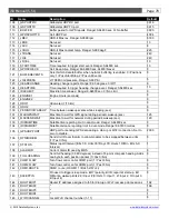
200
I_KWDELAY
Delay after voice call before trying to send data (sec)
30
201
I_RFPING
Time limit (sec) for sending to server after RF ping in poll-only mode
5
202
I_MOTIONDELAY
Motion interval required to wake unit up (in 20ms steps). Range 0-255
25
203
I_MOTIONWAKE
Set g-force required to wake unit up by motion (approx 1/1000 g). Range 1-255 60
204
I_GPSDYN
GPS dynamic mode (0=Portable 2=Stationary 3=Pedestrian 4=Automotive
5=Sea 6=Airborne <1G 7=Airborne <2G 8=Airborne <8G
4
205
I_GPSMINELEV
GPS minimum required satellite elevation (degrees)
5
206
I_GPSPDOP
GPS PDOP mask (in 0.1 increments)
50
207
I_GPSPACC
GPS Accuracy mask (metres)
100
208
I_TIMEZONE
Time zone. Bit 8=Update Logger. Bit 7=Auto Daylight Time. Bit 6=Negative.
Bits 0-4=Time Zone in 15 min steps
468
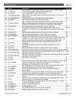
209
I_NMEASPEED
NMEA COM speed. See note below for values
7
210
I_NMEATYPE
Select NMEA sentences. Bit 0=GLL off. Bit 1=GSA off. Bit 2=GSV off. Bit
3=VTG off. Bit 4=GRS on. Bit 5=GST on. Bit 6=DTM on. Bit 7=GBS on
0
211
I_DESCENT
Max allowed descent rate (m/s). Set to zero to disable. Not currently used
0
212
I_IBUTTONSPEED
iButton COM Speed. See note at bottom for values
7
213
I_RFIDSPEED
RFID Tag Reader COM Speed. See note at bottom for values
7
214
I_RFIDTYPE
RFID settings. Bit 0=Report Tags, Bit 1=Driver Logging
1
Table 7
– Integer Settings
COM Speed Values:
1=110, 2=300, 3=600, 4=1200, 5=2400, 6=4800, 7=9600, 8=14400,
9=19200, 10=28800, 11=38400, 12=56000, 13=57600, 14=115200
I/O Settings:
0=General Input, 1=Priority Input (forces i50 awake when active), 11=Alert
Input, 12=Engine On Input, 13=Geofence Input, 14=Driver Check Input,

