background image

i50 Manual (5.51) 

Page 13


© 2018 Datalink Systems, Inc. 

www.datalinksystemsinc.com


4.5 COM Connectors 

The i50 has three external DB-9 serial connections: COM1, COM2 and COM3. These all use RS-232 
voltage levels, with ESD protection. 
 

4.5.1 Automatic Shutdown (version 1 and 2 PCB) 

The COM2 and COM3 ports will not automatically wake up until a valid external RS-232 signal is 
present. Once awake, the ports will shut down immediately when all RS-232 signals have been 
removed. Note: because COM3 shares some lines with the internal Iridium modem, it will always stay 
awake while the Iridium modem is enabled (requires internal Iridium modem to be installed). 
 

Important note for Garmin users: newer NUVI devices also keep their serial ports turned off 
until valid signals are detected. Because of this, 

they will not work correctly with the i50’s 

COM2 port. The COM3 port will only work with these devices if an internal Iridium modem is 
present and enabled. The same applies to any external devices that power down their ports 
when no signal is detected, such as many RS-485 converters. In this case, use COM1.  


4.5.2 Automatic Shutdown (version 3.x PCB) 

The i50 version 3.x PCB automatically enables its COM ports while it is awake, and disables them 
when sleeping. 
 

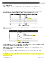
4.5.3 COM1 

COM1 has a female connector, through which the i50 acts as a DCE (data communication 
equipment). This is intended for connection to a PC or other terminal, but can be used for any 
purpose. See Table 3 for pin descriptions. 
 

DB-9 Pin (female) 

Pin Name 

Direction (relative to i50

)


DCD 

Output 

RX 

Output 

TX 

Input 

DTR 

Input 

GND 

DSR 

Output (always high) / VOUT* 

RTS 

Input 

CTS 

Output 

RI 

Output 

Table 3 

– COM1 Connector 

 
COM1 is turned on and off by the i50, based on the Port A route setting. The port is enabled when 
Port A is routed to COM1, and disabled when Port A is routed to the program connector or internal 
Wi-Fi. 
 
* On version 3.x PCBs, the COM1 DSR line is connected internally to the VOUT output, allowing the 
i50 to power an external device. 

Note that the voltage on this line will match the i50’s input 

voltage, which might exceed normal RS-232 levels.


Содержание i50

Страница 1: ...i50 Manual 5 51 Page 1 2018 Datalink Systems Inc www datalinksystemsinc com i50 Manual 5 51 Last updated Friday 5 April 2019...

Страница 2: ...tatus Indicators 12 4 5 COM Connectors 13 4 6 Antenna Connectors 15 5 0 Installation 16 5 1 Cellular SIM Card 16 5 2 Device Orientation 17 5 3 Power Supply 17 5 4 I O Connections 17 5 5 COM Connection...

Страница 3: ...ial Up Configuration 50 10 2 Connection Details 51 11 0 Internal Wi Fi version 3 x PCB 52 12 0 Wi Fi Firmware Update version 3 x PCB 53 13 0 Status Messaging Protocol 54 13 1 Commands sent to i50 54 1...

Страница 4: ...n a manner consistent with the instructions provided Any changes or modifications including the use of non standard antennas not expressly approved by the party responsible for compliance could void t...

Страница 5: ...lar modem FCC ID MIVGSM0308 Iridium modem FCC ID Q639601 Wi Fi module FCC ID PI405W 1 3 2 Version 3 x PCB Cellular modem FCC ID PKRNVWCNN0403 IC 3229A CNN0403 ver 3 1 PCB FCC ID XPYLISAU200 IC 8595A L...

Страница 6: ...dic wakeup timer Wide input voltage range with load dump protection Battery voltage monitoring Four digital inputs plus Ignition input Four digital outputs Two analog inputs Switched power output for...

Страница 7: ...ng COM3 three wire TX RX GND VOUT Output 1 3 A continuous internal resettable fuse Short circuit protection 5 A typical Output voltage Supply voltage 0 6 V at 1 A Digital Inputs Maximum continuous vol...

Страница 8: ...i 250 mW 1 2 W during TX Sleep mode 60 mW5 Digital Outputs 700 mA continuous per output Short circuit protection 1 7 A typical Internal Sat Modem Optional Iridium 9602 Internal Cell Modem Optional Enf...

Страница 9: ...GPS LED GPS status indicator Wi Fi Female SMA connector for Wi Fi antenna optional Iridium Female SMA connector for Iridium antenna optional GPRS Cell Female SMA connector for cellular antenna option...

Страница 10: ...ection 3 0 for detailed specifications on these pins 4 2 VOUT Power Source The VOUT line provides a switched power output allowing the i50 to turn an external device on or off By default VOUT is activ...

Страница 11: ...t VOUT and GND use RS 232 voltage levels RJ 45 Pin Pin Name Direction relative to i50 DB 9 Pin female 1 VOUT Output 2 MODE Input 7 RTS 3 RX Input 3 TX 4 STATUS Output 6 DSR 5 TX Output 2 RX 6 RESET In...

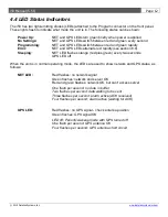
Страница 12: ...see section 6 8 Sleeping NET LED flashes orange red plus green every two seconds GPS LED off When the unit is in normal operating mode the LEDs are used to show network and GPS status as follows NET...

Страница 13: ...ies to any external devices that power down their ports when no signal is detected such as many RS 485 converters In this case use COM1 4 5 2 Automatic Shutdown version 3 x PCB The i50 version 3 x PCB...

Страница 14: ...wire interface so is unable to support hardware handshaking Table 5 shows the COM3 pin descriptions DB 9 Pin male Pin Name Direction relative to i50 1 Not used 2 RX Input 3 TX Output 4 DTR Output alw...

Страница 15: ...se the i50 CPU will reset and stop working until the line is deactivated 4 6 Antenna Connectors The front panel provides Wi Fi Iridium and cellular antenna connectors SMA Each connector will only be p...

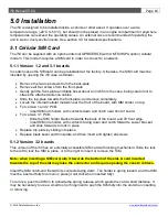
Страница 16: ...y Locate the internal cellular modem near the front of the board with SIM holder on top For version 1 and 2 PCB Insert SIM into holder with contacts down and notch near front of board For version 3 1...

Страница 17: ...t to use battery voltage to detect engine running and use its accelerometer to detect motion to wake up from sleep However it is recommended to connect the IGN input to a vehicle ignition source high...

Страница 18: ...internal modules See section 1 2 for important information about antenna selection Note to allow automatic noise profiling the GPS antenna should be attached BEFORE turning the unit on 5 7 Initial Se...

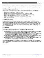
Страница 19: ...n the unit wakes briefly to send its position then goes back to sleep All internal devices are turned on but the VOUT power source is not activated in this mode 6 2 1 Power Up Upon power up the microp...

Страница 20: ...tion and then send this to the server before going straight back to sleep The Max GPS Send Wait Time settings limit the maximum time the unit is awake in case there is no GPS or network coverage 6 3 M...

Страница 21: ...wer cost modem When no network is available or the i50 has been configured to buffer reports the outgoing packets will be stored in memory for transmission at a later time 6 6 Data Queue The i50 keeps...

Страница 22: ...nd point to point RF networks to acknowledge receipt of the data These ACKs will add 4 bytes 32 including UDP cellular datagram Note when the i50 has buffered multiple positions in memory the overall...

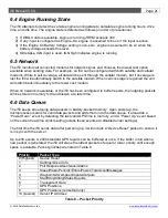
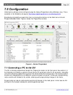
Страница 23: ...necting a PC to the i50 The i50 is normally programmed through the Program connector on the front panel See section 4 3 for information on making a cable to connect from a PC serial port to the RJ 45...

Страница 24: ...iSeries Programmer will prompt for the password before continuing If the password is not entered there is no way to read or write settings to the i50 If the password is forgotten use the Device Facto...

Страница 25: ...bar is displayed to warn of the mismatch This provides a quick method of tracking changes before they have been sent to the asset At any time the current asset values can be copied into the local val...

Страница 26: ...latile memory so they will be retained if the power supply is removed even if the internal backup battery is flat When finished programming use the Start Device button to have the i50 exit programming...

Страница 27: ...Time Clock RTC to match the PC s clock Note that the programmer determines the time in UTC format so that it is written correctly no matter what time zone the PC is in Reset Accel Cause the i50 to aut...

Страница 28: ...option is set under the Sleep Pin setting before unit enters sleep mode Set to zero to disable sleep mode Periodic Wakeup While sleeping the unit can wake periodically to send its location Set to zer...

Страница 29: ...l the next report is triggered City Time Reports Used to enable periodic position reports in City mode Options are provided to disable these reports when IGN is off or device is stationary City Max Ti...

Страница 30: ...ion Start Time Period unit must remain moving to trigger a Start event or tow alert Use Accel to detect motion If enabled the unit will use g force readings to detect when the unit is moving rather th...

Страница 31: ...a is sent immediately Cell Buffer Enable position buffering when using a cellular modem See note on RF Buffer setting Iridium Buffer Enable position buffering when using Iridium See note on RF Buffer...

Страница 32: ...from GPS RMC and GGA packets are always enabled Cellular Cell COM Speed Cellular modem COM speed Cell Modem Type Type of cellular modem Cell Server Domain Name Optional domain name for server When en...

Страница 33: ...ed the i50 will select the current radio channel zone based on waypoint locations Kenwood Base TX Fleet Type Kenwood base radio fleet ID Fleetsync or ID type NXDN Together with the Kenwood TX Base ID...

Страница 34: ...Key Selects encryption key for Ezurio Wi Fi interface version 1 and 2 PCB Enter 10 hex digits for a 64 bit key 26 hex digits for a 128 bit key or leave blank for no encryption Dial up Msg Dial up Fire...

Страница 35: ...he standard serial encoding allowing connection to a sign using a serial to Ethernet adapter Transparent Data Transparent COM Speed Transparent COM speed Transparent Serial Config COM settings for tra...

Страница 36: ...ates how far the front of the device Program connector end has been rotated away from the front of the vehicle in a level plane Set to zero to calibrate automatically Select Uncalibrated to disable ca...

Страница 37: ...output states to match the current RF zone voice or data are treated the same In this case all channel selection outputs will be inactive when the i50 is outside all RF zones The i50 Programmer has a...

Страница 38: ...ese tags can be 16 character iButton IDs or 8 character RFID tag IDs When the list is empty or not supported as with firmware version 5 57 the i50 will accept any driver tag Otherwise it will only acc...

Страница 39: ...OUT driver ADC Status of internal analog to digital converter ADC Accel Status of internal 3D accelerometer Buffer Shows how many events or positions are currently stored in memory This buffer can be...

Страница 40: ...rt button The screen acts as a simple terminal showing data received and allowing data to be sent by typing The Close Port button closes the port and the Binary option is used to display all incoming...

Страница 41: ...wood sends an encoded data packet to check for a radio response The APC1 2 commands are used to check automatic people counters 7 4 1 Direct Mode The Direct Mode checkbox causes the i50 to map the cur...

Страница 42: ...assuming a full handshaking cable is being used The Outputs frame allows the i50 digital outputs VOUT line and COM2 3 ports to be turned on and off for testing purposes Note any changes made to outpu...

Страница 43: ...ng device such as a laptop to the modem This allows the laptop to access the Internet for email file transfer etc The dial up port acts as a modem emulator Any external device can send AT commands to...

Страница 44: ...values exceed a predefined range Current firmware is designed to talk to adapters that use the ELM 327 chipset 8 7 Alarm Interface This is a custom option to allow the i50 to control an external alarm...

Страница 45: ...nal An internal Iridium modem is available as an i50 option 8 12 Ezurio i50 version 1 and 2 PCBs have the option of an internal Ezurio Wi Fi module This module allows third party devices to connect to...

Страница 46: ...0 will check its location every minute to determine whether it is within an RF zone see section 7 2 4 If it is within two or more zones the i50 will select the closest one Once the zone has been deter...

Страница 47: ...to detect motion When enabled the i50 will base its start stop state on the accelerometer output rather than using GPS signal This will create more reliable start stop reports as it will work in area...

Страница 48: ...in degrees relative to the starting position shown in Figure 8 Figure 8 Accelerometer Angles With all values near zero the i50 orientation has the power connector on red side in illustration facing f...

Страница 49: ...nd y angles to self level itself Calibration mode can be completed in two ways 1 Manually by setting the accelerometer z angle setting 156 to a non zero value The z angle controls which direction is f...

Страница 50: ...tandard 19200 bps Modem under the Standard Modem Types group 5 Select the PC COM port where the i50 will be connected Note that if you are going to use a USB to serial converter it must be plugged in...

Страница 51: ...r Timeout period This allows a computer to keep its dial up connection active at all times Note the computer should be configured to reduce network traffic preferably using a firewall as satellite air...

Страница 52: ...this packet to detect the i50 s IP address and listening port To send data devices will connect to the i50 s SSID and then open a TCP IP connection to the i50 It is expected that the normal use for t...

Страница 53: ...reboot enter to restart the module 6 Click on the Wi Fi 9600 button to switch to 9600 bps 7 Type rapidly to enter command mode A CMD response indicates that the modem is ready to accept commands 8 Typ...

Страница 54: ...s format is the file transfer command response packets which include binary data and use a length value to determine packet size see section 13 3 for details The ESC character 0x1B can be sent to canc...

Страница 55: ...ssage is an email Message Message body FileData See section 13 3 Error 0 Unknown command 1 No ID 2 Invalid ID 3 Unknown ID 4 Wrong network for file transfer 5 File data too long Net 0 None 1 MSAT 3 Ra...

Страница 56: ...address 255 255 255 255 when connecting via dial up or Wi Fi When the i50 replies its IP address will be contained in the from address of the response Further packets can then be sent directly to the...

Страница 57: ...t WebGate user Subject Email subject if message is an email User name if message is from a DataHost WebGate user Address Email address if message is an email Message Message body When such a command i...

Страница 58: ...ted string Name of file 2 Offset 3 bytes LSB Offset of this data block within file Starts at 1 Length 2 bytes LSB Length of this data block 1024 maximum RawData Raw file data 3 ACK Offset 3 bytes LSB...

Страница 59: ...amples 1 Check status i50 response shows it has an active cellular connection it is currently transmitting data and has 5 packets waiting in its buffer TX N ETX RX n CTRL Z 11 CTRL Z 0 CTRL Z 0 CTRL Z...

Страница 60: ...omatically populated with one or more messages when the Garmin is connected This list provides a way to request the current i50 status network GPS and pager states If a Grace system is enabled another...

Страница 61: ...ith the Check Bus Output digital output mode This input indicates that the driver has checked a bus for remaining passengers Each input has a polarity setting which indicates the active state high or...

Страница 62: ...iver Beeper Output pulses regularly while IGN is turned on and no driver is logged in Output chirps twice when a driver logs in using a recognised iButton RFID tag or three times if an unrecognised iB...

Страница 63: ...Select 2 Channel Select 1 1 Inactive Inactive Inactive Active 2 Inactive Inactive Active Inactive 3 Inactive Inactive Active Active 4 Inactive Active Inactive Inactive 5 Inactive Active Inactive Activ...

Страница 64: ...is state is also triggered when a Grace pager alert is received The alarm must be cancelled before another alarm can be sent Even if a server ACK is received alarms will be resent every 5 min until a...

Страница 65: ...irmware updates may reset the i50 s internal data buffer If the buffer contains important information please ensure that the unit has connected to a server and sent its buffer before updating firmware...

Страница 66: ...onnecting and check the Use USB to Serial Converter option if appropriate If problems persist try setting the Stop Bits to 1 Figure 11 RFU Communications Options Use the File Load flash image menu to...

Страница 67: ...ettings contain ranges of bits For example a setting may contain a value in Bits 7 5 7 to 5 This uses three bits to define the value ranging from 000 to 111 decimal 0 to 7 If this value is set to 4 bi...

Страница 68: ...0 38 I_USEDISTLO Use city distance reports 1 Yes 0 No 0 39 I_USEDISTHI Use highway distance reports 1 Yes 0 No 0 40 I_USETIMELO Use city time reports Bit 0 Enable Bit 1 Don t send while IGN off Bit 2...

Страница 69: ...0 84 I_DEBOUNCE1 Input 1 debounce Range 20 30000 ms 100 85 I_DEBOUNCE2 Input 2 debounce Range 20 30000 ms 100 86 I_DEBOUNCE3 Input 3 debounce Range 20 30000 ms 100 87 I_DEBOUNCE4 Input 4 debounce Rang...

Страница 70: ...n wakeup events while sleeping sec 0 131 I_MAXGPSWAIT Max time to wait for GPS signal during periodic wakeup sec 120 132 I_MAXSENDWAIT Max time to wait for network during periodic wakeup sec 120 133 I...

Страница 71: ...to zero to recalibrate 0 162 I_ACCELY Accelerometer rotation around Y axis radians 10000 Set to zero to recalibrate 0 163 I_MAXTILT Max allowed tilt when stationary degrees Set to zero to disable 45 1...

Страница 72: ...i Fi port TCP listening port for local access point or UDP remote port for connecting to external network 4004 200 I_KWDELAY Delay after voice call before trying to send data sec 30 201 I_RFPING Time...

Страница 73: ...TR_WEPKEY WEP key for Ezurio connection First two characters define encryption type 00 No Security 01 64 bit 02 128 bit The key starts at third character 64 bit keys use 10 hex characters 128 bit keys...

Страница 74: ...i50 Manual 5 51 Page 74 2018 Datalink Systems Inc www datalinksystemsinc com 18 0 Contact Information For further support email support datalinksystemsinc com...

Страница 75: ...APN with the APN defined by the network operator AT AREG 2 Enables auto registration AT W Saves modem settings AT RESET Resets modem AT CREG Checks GSM registration If working OK response should be C...

Отзывы: