background image


Datacolor CONDITIONER™ (MB2) 06/2017


page 54/126 


Program editor: “Edit program” menu 

Select the desired function and press the 

Confirm


icon. 

The program editor offers following options: 

  Change the program name 

  Copy program  

  Replace program: Replacing an new or an existing program with the copied program. This menu point 

is visible only after a program has been copied. 

  Delete program   

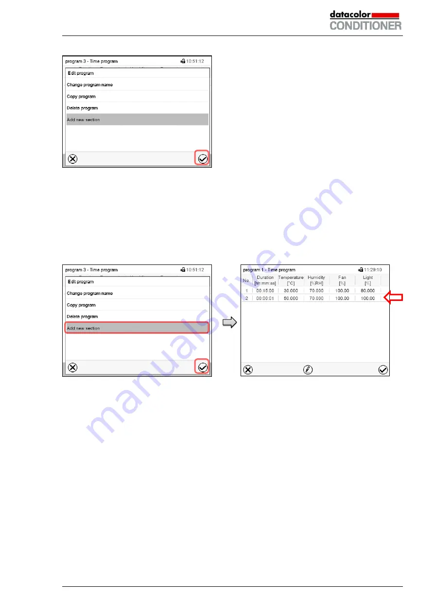
  Add new section 


To add a new section, select “Add new sec-
tion” and press the 

Confirm

 icon. 

The program view opens. 


Program view (example: cabinet with lights). 

A new section is always added at the very bot-
tom (example: section 2).  


9.5.1  Deleting a time program 

Path: 

Main menu > Programs > Time program 

In the “Time program” menu select the program to be deleted. The program view opens. 

In the 

program


view

 press the 

Edit

 icon to open the program editor 

In the 

program


editor

 select “Delete program” and press the 

Confirm

 icon.  

The program is deleted. The controller returns to the program view. 


Содержание 9020-0129

Страница 1: ... 2017 Art No 7001 0346 Operating Manual Original operating manual Datacolor CONDITIONER Sample conditioning cabinet with display controller MB2 9020 0129 9120 0129 without lights 9020 0190 9120 0190 with lights ...

Страница 2: ...stallation and ambient conditions 21 4 INSTALLATION AND CONNECTIONS 22 4 1 Spacer for wall distance 22 4 2 Wastewater connection 23 4 3 Freshwater supply 23 4 3 1 Automatic fresh water supply via water pipe 24 4 3 2 Manual fresh water supply via external freshwater can option 26 4 4 Optional water treatment system BINDER Pure Aqua Service 26 4 5 Optional external freshwater and wastewater cans 26 ...

Страница 3: ...the end of the program 52 9 4 Creating a new time program 53 9 5 Program editor program management 53 9 5 1 Deleting a time program 54 9 6 Section editor section management 55 9 6 1 Add a new program section 56 9 6 2 Copy and insert or replace a program section 56 9 6 3 Deleting a program section 57 9 7 Value entry for a program section 58 9 7 1 Section duration 58 9 7 2 Set point ramp and set poi...

Страница 4: ...rd change 85 13 5 1 Password change 85 13 5 2 Deleting the password for an individual authorization level 87 13 5 3 New password assignment for service or admin authorization level when the password function was deactivated 88 13 6 Activation code 89 14 GENERAL CONTROLLER SETTINGS 90 14 1 Selecting the controller s menu language 90 14 2 Selecting the temperature unit 90 14 3 Setting date and time ...

Страница 5: ... member states of the EU 117 22 TROUBLESHOOTING 118 23 TECHNICAL DESCRIPTION 120 23 1 Factory calibration and adjustment 120 23 2 Over current protection 120 23 3 Definition of usable volume 120 23 4 Technical Data 121 23 5 Equipment 122 23 6 Spare parts extract 123 23 7 Dimensions size 115 124 24 EU DECLARATION OF CONFORMITY 125 All efforts have been made to ensure the accuracy of the information...

Страница 6: ...bserving the instructions in this operating manual are prerequisites for hazard free use and safety during operation and maintenance In no event shall Datacolor be held liable for any dam ages direct or incidental arising out of or related to the use of this manual This operating manual cannot cover all conceivable applications If you would like additional information or if special problems arise ...

Страница 7: ...rty in its proximity 1 2 2 Safety alert symbol Use of the safety alert symbol indicates a risk of injury Observe all measures that are marked with the safety alert symbol in order to avoid death or injury 1 2 3 Pictograms Warning signs Electrical hazard Hot surface Explosive atmosphere Stability hazard Lifting hazard Scalding hazard High humidity Danger of frost Risk of corrosion and or chemical b...

Страница 8: ...tion Instruction how to avoid the hazard mandatory action Observe all other notes and information not necessarily emphasized in the same way in order to avoid disruptions that could result in direct or indirect injury or property damage 1 3 Localization position of safety labels on the cabinet The following labels are located on the cabinet Pictograms warning signs Hot surface inner glass door abo...

Страница 9: ...ial application acc to project no 2 0 kW Nominal power 8 4 A Nominal current 200 240 V 50 Hz Nominal voltage range 10 at the indicated power frequency 200 240 V 60 Hz 2 Current type Max operating pressure 15 bar Max operating pressure in the refrigerating system 15 bar 218 PSI R 134A 0 180 kg Refrigerant type and filling weight Contains fluorinated greenhouse gases covered by the Kyoto Protocol Sy...

Страница 10: ...thorized by the Datacolor who have undergone appropriate electrical training and who have carefully read the cabinet service and operating manuals To operate the cabinet use only original Datacolor accessories or accessories from third party suppliers authorized by Datacolor The user is responsible for any risk caused by using unauthorized accessories CAUTION Danger of overheating Damage to the ca...

Страница 11: ...s and were routinely tested in accordance to VDE 0411 1 IEC 61010 1 During and shortly after operation the temperature of the inner surfaces almost equals the set point CAUTION The glass doors the glass door handles the inner chamber and the light cassettes cabinet with lights will become hot during operation Danger of burning Do NOT touch the glass doors the inner surfaces the light cassettes or ...

Страница 12: ...to release of toxic gases The charging material shall not contain any corrosive ingredients that may damage the ma chine components made of stainless steel aluminum and copper Such ingredients include in particular acids and halides Any corrosive damage caused by such ingredients is excluded from liability by Datacolor WARNING If customer should use a cabinet running in non supervised continuous o...

Страница 13: ...ate temperature exceeding Safety measurement and control equipment The safety measuring and control equipment is easily accessible Electrostatic charge The interior parts are grounded Non ionizing radiation Non ionizing radiation is not intentionally produced but released only for technical reasons by electri cal equipment e g electric motors power cables solenoids The machine has no permanent mag...

Страница 14: ...rmanent load Substance Formula ppm mg m3 ppm mg m3 Ammonia NH3 20 14 5500 4000 Acetone CH3COCH3 500 1200 3300 8000 Benzene 300 1200 150000 Chlorine Cl2 0 5 1 5 0 7 2 Acetic acid CH3COOH 10 25 800 2000 Ethyl acetate CH3COOC2H5 400 1400 4000 15000 Ethanol C2H5OH 500 960 3500 6000 Ethylene glycol HOCH2CH2OH 10 26 1200 3000 Formaldehyde HCHO 0 3 0 37 2400 3000 Isopropanol CH3 2CHOH 200 500 4800 12000 ...

Страница 15: ...nt tubes Control is effected via the MB2 controller Light is dimmable in 1 steps The inner chamber the pre heating chamber and the interior side of the doors are all made of stainless steel V2A German material no 1 4301 US equivalent AISI 304 The housing is RAL 7035 powder coated All corners and edges are also completely coated The inner chamber is closed by a glass door that enables the samples t...

Страница 16: ...r H to 70 r H For the control ranges of temperature and humidity see climatic diagram chap 17 Standard temperature and humidity settings for sample conditioning are typically 21 C and 65 r H 2 1 Cabinet overview Figure 3 Datacolor CONDITIONER sample conditioning cabinet A Instrument box B Door handle C Outer door D Lower front cover refrigerating machine and humidity generation module A B C D ...

Страница 17: ...play with touchscreen USB interface Pilot lamp Figure 4 Instrument panel with MB2 program controller and USB interface 2 3 Lateral control panel 1 2 Figure 5 Lateral control panels at the right side of the refrigerating humidity generation module 1 Main power switch 2 Ethernet interface ...

Страница 18: ... Figure 6 Water connections on the cabinet rear 3 Socket for optional freshwater can chap 4 5 4 Power cable 5 Purging outlet for humidifying module for service purpose only 6 Freshwater connection IN with screw thread for hose with union nut 7 Wastewater connection OUT with hose olive for hose ...

Страница 19: ...ng heavy loads Do NOT lift or transport the cabinet using the door the handle or the lower housing Lift the cabinet from the pallet at the four lower corners with the aid of four people If you need to return the cabinet please use the original packing and observe the guidelines for safe lift ing and transportation chap 3 2 For disposal of the transport packing see chap 21 1 3 2 Guidelines for safe...

Страница 20: ...system 10 C 14 F to 60 C 140 F With temperatures below 3 C 37 4 F water must be completely removed from the humidifying sys tem CAUTION Storage below 3 C 37 4 F with filled steam humidifying system Freezing in the steam generator Damage to the cabinet Contact your local Datacolor service representative before any transportation below 3 C 37 4 F Permissible ambient humidity max 70 r H non condensin...

Страница 21: ...rature set points below ambient temperature high ambient humidity may lead to condensation on the cabinet Installation height max 2000 m 6562 ft above sea level A water tap 1 bar to 10 bar is necessary for the installation of the humidification system chap 4 3 If no suitable in house water connection is available you can manually supply water by filling the freshwater can option chap 4 5 To avoid ...

Страница 22: ...t you must close the tap of the water supply Install the cabinet in a way that the freshwater supply is easily accessible In case of a prolonged temporal decommissioning Leave the cabinet door open or remove the access port plugs 4 Installation and connections 4 1 Spacer for wall distance Please fix both spacers with the supplied screws at the cabinet rear This serves to ensure the prescribed mini...

Страница 23: ...abinet to a freshwater pipe or filling the freshwater can option chap 4 5 You can supply the cabinet with freshwater via a water pipe or by manually filling a freshwater can op tion chap 4 5 Water intake temperature NOT below 5 C 41 F and not exceeding 40 C 104 F CAUTION Calcification of the humidifying system Damage to the cabinet Operate the cabinet with deionized demineralized water only Types ...

Страница 24: ...ntinuous water flow Supply pressure 1 to 10 bar when connecting to a water pipe Water type deionized demineralized water Water intake temperature NOT below 5 C 41 F and not exceeding 40 C 104 F The water intake should be provided with a shut off slide or water tap For the water supply fix the delivered adapter with hose olive on the thread at the rear of the cabinet Protect the water supply at one...

Страница 25: ...it is manually released Release of the reflux protection device In case the burst protection device has interrupted the water supply first find the reason and remove it as necessary Close the water tap Release the valve by a half left turn of the upper knurled part You can hear the release of the valve as a clicking noise Tighten the burst protection device against the water tap by a right turn Op...

Страница 26: ...er treatment system disposable unit is available to treat tap water The lifetime of the unit depends on water quality and the amount of treated water used The measuring equipment to assess the water quality is reusable For detailed information on installing and operating the water treatment system BINDER Pure Aqua Service please refer to the operating manual Art No 7001 0269 coming with BINDER Pur...

Страница 27: ...on its 4 carriers You can install it either at the left or the right side Cable connection 8 Freshwater hose connection 9 Figure 11 Freshwater can option 2 Cable connections Connect the plug of the cable to the socket 3 at the rear of the cabinet The socket 3 is marked with a sticker Socket 3 7 6 Figure 12 Connections at the cabinet rear ...

Страница 28: ...the freshwater can option at the end of each day 4 5 2 Mounting the wastewater can 1 Fixing if required Hang the can with its holding device on its 4 carriers at the free space next to the freshwater can 2 Hose connections Plug the wastewater hose to the hose connection 10 of the wastewater can and secure it with a hose clamp You can use a part of the standard supplied water hose Hose connection o...

Страница 29: ...e freshwater can if required Hang the can with its holding device on its 4 carriers You can install it either at the left or the right side 2 Cable connections of the freshwater can Connect the plug of the cable to the socket 3 at the rear of the cabinet as described in chap 2 4 3 Hose connections Plug the wastewater hose into the hose connection 11 of the freshwater can and secure it with a hose ...

Страница 30: ...r position 4 7 Electrical connection The cabinets are supplied ready for connection They come with a fixed power connection cable of at least 1800 mm 70 87 in in length Power plug NEMA 6 20P Voltage 10 at the indicated power frequency 200 240 V at 50Hz 200 240 V at 60Hz Current type 2 Cabinet fuse 16 Amp The domestic socket must also provide a protective conductor Make sure that the connection of ...

Страница 31: ...type plug for appropriate construction and if it is undamaged 4 8 Connection of the optional voltage changer The voltage changer enables the cabinet to operate at a power frequency of 115 Volt It is packed sepa rately and supplied together with the cabinet The voltage changer is supplied with a fixed power connection cable with a NEMA 5 20P plug It is pro tected against excess current with an inte...

Страница 32: ...c tor 3 Turn on the voltage changer at the power switch C position I The green pilot lamp B lights up 4 Turn on the cabinet with the main power switch 1 in the lateral control panel Position 0 off Position I on Figure 16 Power switch of the voltage changer Dimensions of the voltage changer Width mm 255 Depth without door handles mm 360 Depth incl cable and door handles mm 450 Height mm 300 Length ...

Страница 33: ... controller offers programming week and time programs In addition there is a timer program available stopwatch function The controller offers various notifications and alarm messages with visual and audible indication and remote alarms via e mail an event list trace file and the graphical display of the measuring values in the in der chart recorder view The MB2 program controller permits programmi...

Страница 34: ...lues Functional icons Figure 17 Normal display of the MB2 program controller sample values cabinet without lights Operating mode Temperature values Humidity values Light intensity values Actual values Set point values Functional icons Figure 18 Normal display of the MB2 program controller sample values cabinet with lights ...

Страница 35: ...icons Date time authorization level of the logged in user memory Quick setpoint entry Continue to next screen Back to Normal display Information Program start Setpoint entry Event list Display of active alarms Access to main menu Figure 19 Operating functions of the MB2 controller in normal display example values for cabinet with lights ...

Страница 36: ...en normal display program display and chart recorder display Press the Normal display icon to return from program display and chart recorder display back to Normal display Normal display actual values setpoint values Cabinet without lights Cabinet with lights Program display example time program Chart recorder display Cabinet without lights Cabinet with lights ...

Страница 37: ... week program Information Information on program operation setpoints actual values and the safety controller Normal display Return from program display or chart recorder display to Normal display Change view Toggle between Normal display program display and chart recorder display Functional icons in individual menus Icon Signification Function Back Return from each menu to Normal display Update Up...

Страница 38: ... Go to Zoom submenu in the history display to select the zoom factor Show scroll buttons Show scroll buttons in the history display to scroll to an instant Hide scroll buttons Hide scroll buttons in the history display to scroll to an instant Information icons referring to chamber conditions Icon Text information Condition Idle mode Controller in Idle mode Temperature range Current actual temperat...

Страница 39: ...emperature and humidity fan speed and light intensity cabinet with lights can be defined which are then maintained until the next manual change chap 7 1 Timer program operation Stopwatch function during an entered duration the controller constantly equilibrates to the setpoints entered in Fixed value operation mode Time program operation An entered time program for temperature humidity fan speed a...

Страница 40: ...word protection Main menu program settings further information Service submenu The Settings submenu allows general configuration of the controller chap 5 5 1 List of active alarms chap 11 Access to the event list chap 15 2 Setpoint entry for Fixed value operation turning on off humidity control safety controller settings chap 7 6 3 12 2 Start pause cancel an already entered respectively a running ...

Страница 41: ... information chap 15 2 Settings submenu not visible for user with User authorization level chap 14 Program entry submenu for time and week programs chap 9 and 10 Service submenu chap 5 5 3 Datacolor service contact page chap 15 1 Calibrating the touch screen chap 14 4 2 Back to Normal Display Settings submenu Settings of many general controller functions and network settings chap 14 Available only...

Страница 42: ... 2 Setting the tolerance range and delay time for tolerance range alarm chap 11 4 Entry of the MAC address and IP address chap 14 5 1 Password protection for web server access chap 14 5 2 Configuration of the e mail server assign ment of e mail addresses chap 14 5 3 Back to main menu 5 5 3 Service submenu The Service submenu is available for users with Service or Admin authorization level When log...

Страница 43: ...tions return to the same status the cabinet had before power failure The controller continues to function in the original operating mode it was in previously before the power failure occurred Performance after power failure in Idle mode Control is deactivated Performance after power failure in Fixed value operation mode All functions return to the same status the cabinet had before power failure T...

Страница 44: ...er an interruption of the power supply the relative humidity will increase after a delay of about 20 minutes as the fresh water needs to be heated first During this period the relative humidity can drop considerably The cabinet may release odors in the first few days after commissioning This is not a quality defect To reduce odors quickly we recommend heating up the cabinet to its nominal temperat...

Страница 45: ... is required to operate the controller chap 13 2 Operation without user log in without password protection If the password function has been deactivated after turning on the unit without user log in there are those controller functions available which correspond to the highest authorization level without a password protection There is no lock icon in the header 6 3 Turning on off humidity control ...

Страница 46: ...out humidity 10 C 50 F up to 50 C 122 F with humidity Humidity 0 r H up to 70 r H 10 r H to 70 r H see climatic diagrams chap 17 Light intensity 0 to 100 Fan speed 40 up to 100 Reduce the fan speed only if required because the spatial distribution of temperature and humidity will also be reduced Technical data refers to 100 fan speed For the control range of temperature and relative humidity see t...

Страница 47: ... without lights Setting range 0 r H up to 80 r H Cabinet with lights Setting range 0 r H up to 70 r H Confirm entry with Confirm icon Select the field Fan and enter the desired fan speed setpoint Setting range 40 up to 100 fan speed Confirm entry with Confirm icon Cabinet with lights Select the field Light and enter the desired light intensity setpoint Setting range 0 up to 100 light intensity Wit...

Страница 48: ...6 operation lines control contacts They are used to activate deactivate special controller functions Operation line Humidity off serves to turn off the humidity Operation line Idle mode activates deactivates the operating mode Idle mode The other operation lines are without function Use the Setpoints menu to configure the operation lines Setpoints menu example cabinet with lights Select the field ...

Страница 49: ...ter the desired program duration Press the Confirm icon Select the field Program start and enter the desired start time of the program Press the Confirm icon The program delay time until program start begins Normal display Information on the bottom of the screen indicates the currently running program and the time already passed The grey bar shows how much time of the whole time is elapsed 8 1 1 P...

Страница 50: ...icon to cancel the program A confirmation prompt is displayed Press the Confirm icon to confirm that the program shall really be cancelled After confirming the message the controller changes to Fixed value operation mode Temperature and humidity will then equilibrate to the setpoints of Fixed value operation mode 8 3 Performance after the end of the program After the end of the program the message...

Страница 51: ...ograms Time program 9 1 Starting an existing time program In Normal display press the Program start icon to access the Program start menu Program start menu In the field Program type select the setting Time program In the field Program select the desired program Select the field Program start and enter the desired program start time Press the Confirm icon The program delay time until program start...

Страница 52: ...am Press the Program cancelling icon to cancel the program A confirmation prompt is displayed Press the Confirm icon to confirm that the program shall really be cancelled After confirming the message the controller changes to Fixed value operation mode Temperature and humidity will then equilibrate to the setpoints of Fixed value operation mode 9 3 Performance after the end of the program After th...

Страница 53: ...he program view opens chap 9 5 9 5 Program editor program management Path Main menu Programs Time program Time program menu overview of the existing programs Select an existing program example program 3 or create a new program chap 9 4 The program view opens Program view example for cabinet with lights program 3 If a new program has been created there is just one program section There are the foll...

Страница 54: ...m Add new section To add a new section select Add new sec tion and press the Confirm icon The program view opens Program view example cabinet with lights A new section is always added at the very bot tom example section 2 9 5 1 Deleting a time program Path Main menu Programs Time program In the Time program menu select the program to be deleted The program view opens In the program view press the ...

Страница 55: ...rameter to enter or modify the according value chap 9 7 Press the Edit icon to open the program editor Section editor Edit section menu Select the desired function and press the Confirm icon The section editor offers following options Copy section Replace section Replacing an existing section with the copied section This menu point is visible only after a section has been copied Insert section Add...

Страница 56: ...gram view example cabinet with lights Select the program section to be copied example section 1 Section view example section 1 Press the Edit icon to open the section editor Section editor Edit section menu Select Copy section and press the Confirm icon The current section example section 1 is copied The controller returns to the section view Section view example section 1 Press the Close icon to ...

Страница 57: ... icon to open the section editor Section editor Edit section menu Select Replace section to replace the selected section with the copied section or Select Insert section to additionally add the copied section In this case select whether to insert it before or after the selected section Press the Confirm icon 9 6 3 Deleting a program section In the program view select the program section to be dele...

Страница 58: ...ation lines Repeating one or several sections within a program Temperature setpoint Temperature tolerance range minimum and maximum Humidity setpoint Humidity tolerance range minimum and maximum Fan speed The setting and control ranges for the individual parameters are the same as for Fixed value operating mode chap 7 9 7 1 Section duration Section view partial view Select the field Duration indic...

Страница 59: ... changes of temperature and humidity Steps can be programmed in ramp mode as temperature or humidity changes ramps that occur dur ing a very short interval If the duration of this transitional program section is very short minimum en try 1 sec the temperature or humidity change will proceed rapidly within the minimum amount of time Step mode Sudden changes of temperature and humidity The set point...

Страница 60: ...amp 8 00 00 01 20 0 xxxx xxxx Ramp 9 7 3 Special controller functions via operation lines You can define the switching state of up to 16 operation lines control contacts They are used to activate deactivate special controller functions Operation line Humidity off serves to turn off the humidity Operation line Idle mode activates deactivates the operating mode Idle mode The other operation lines ar...

Страница 61: ... H Confirm entry with Confirm icon The controller returns to the section view Select the field Fan and enter the desired fan speed setpoint Setting range 40 up to 100 fan speed Confirm entry with Confirm icon The controller returns to the section view Cabinet with lights Select the field Light and enter the desired light intensity setpoint Setting range 0 up to 100 light intensity With setting 0 t...

Страница 62: ...roller returns to the section view If one of the actual values temperature and or humidity is outside the program tolerance range the whole program course is interrupted During this program interruption time the controller equilibrates to the set points of the current section The screen header indicates Program pause tolerance band The program runtime indication flashes and does not proceed any fu...

Страница 63: ...efore the currently selected section Confirm entry with Confirm icon The controller returns to the section view 9 7 7 Saving the time program Section view After the all desired values of the program section have been configured press the Con firm icon to take over the programming The controller changes to the program view Program view example cabinet with lights Press the Confirm icon to take over...

Страница 64: ...ams After completing the settings press the Confirm icon to take over the entries and exit the menu The program starts running If instead you press the Close icon to exit the menu without taking over the entries the program will not start After starting the week program the previously entered week program setpoints are active and will be equilibrated according to the current time Information on th...

Страница 65: ...n empty program place Enter the program name and if desired addi tional program information in the correspond ing fields Press the Confirm icon The pro gram view opens Program view For the first section no weekday is specified Therefore the section is first marked in red and cannot be saved Note for cabinet with lights The light setpoint is not visible in the week program view ...

Страница 66: ...llowing options Select a program section to open the section editor chap 0 Press the Edit icon to open the program editor Program editor Edit program menu Select the desired function and press the Confirm icon The program editor offers following options Change program name This menu also offers to configure the ramp step mode setting chap 10 6 1 Copy program Replace program Replacing an new or an ...

Страница 67: ...the very bottom example section 3 When the section start is speci fied the sections are automatically arranged in the correct chronological order 10 4 1 Deleting a week program Path Main menu Programs Week program In the Week program menu select the program to be deleted The program view opens In the program view press the Edit icon to open the program editor In the program editor select Delete pr...

Страница 68: ...to enter or modify the ac cording value chap 10 6 Press the Edit icon to open the program editor Section editor Edit section menu Select the desired function and press the Confirm icon The section editor offers following options Copy section Replace section Replacing an existing section with the copied section This menu point is visible only after a section has been copied Insert section Adding th...

Страница 69: ...e section 3 When the section start is speci fied the sections are automatically arranged in the correct chronological order 10 5 2 Copy and insert or replace a program section Section editor Edit section menu Select Copy section and press the Confirm icon The current section example section 1 is copied The controller returns to the program view Program view Select the section to be replaced or bef...

Страница 70: ...In the section editor select Delete section and press the Confirm icon The section is deleted The controller returns to the section view 10 6 Value entry for a program section Path Main menu Programs Week program Select the desired program and section The setting and control ranges for the individual parameters are the same as for Fixed value operating mode chap 7 10 6 1 Set point ramp and set poi...

Страница 71: ... 2 Weekday Section view example cabinet with lights In the field Weekday select the desired weekday With Daily selected this section will run every day at the same time 10 6 3 Start time Section view example cabinet with lights Select the field Moment Entry menu Moment Select with the arrow keys the desired start moment of the section and press the Confirm icon ...

Страница 72: ...100 fan speed Confirm entry with Confirm icon The controller returns to the section view Cabinet with lights Select the field Light and enter the desired light intensity setpoint Setting range 0 up to 100 light intensity With setting 0 the light is off Confirm entry with Confirm icon The controller returns to the section view 10 6 5 Special controller functions via operation lines You can define t...

Страница 73: ...hereas the alarm will continue until man ual acknowledgement Press the flash icon next to the information icon to access the corresponding text information Normal display showing the text information The currently valid information texts are high lighted in black example Idle mode Condition Information icon Text information Start after condition occurred The controller is in Idle mode chap 5 4 Idl...

Страница 74: ...service representative Humidity system immediately The humidity module cannot fill up In case of freshwater supply via water pipe The water tap is closed or the cabinet is defective e g inlet valve of humidity module In case of freshwater supply via freshwater can option chap 4 5 Water can is empty Humidification is turned off In case of refrigerating operation the interior is strongly dehu midifi...

Страница 75: ...tain condition 11 3 Resetting an alarm list of active alarms Normal display in state of alarm example for cabinet with lights Press the Alarm icon List of active alarms Press the Reset alarm icon Pressing the Reset alarm icon mutes the buzzer for all active alarms The icon then disappears Acknowledging while the alarm condition persists Only the buzzer turns off The visual alarm indica tion remain...

Страница 76: ...midity range and enter the desired value for the humidity range Setting range 5 r H to 20 r H Confirm entry with Confirm icon After completing the settings press the Confirm icon to take over the entries and exit the menu or press the Close icon to exit the menu without taking over the entries If there are actual values outside the tolerance range the following information icons for the correspond...

Страница 77: ...act an authorized service provider or your local Datacolor service representative 12 2 Overtemperature safety controller class 3 1 The cabinets are regularly equipped with an electronic overtemperature safety controller temperature safety device class 3 1 according to DIN 12880 2007 The safety controller is functionally and electrically independent of the temperature control system If an error occ...

Страница 78: ...ly with every set point change This setting is recommended for program operation It is important to check the safety controller set point and safety controller mode occasionally as it does not offer a fix independent limit temperature value which would never be exceeded Example Desired temperature value 21 C desired safety controller value 25 C Possible settings for this example Temperature set po...

Страница 79: ...in the state of alarm The state of alarm is indicated visually in Normal display by the alarm message Safety controller alarm and the screen header flashing in red color If the buzzer is enabled chap 11 5 there is an additional audible alert chap 11 2 The alarm remains active until it is acknowledged on the controller and the inner temperature falls below the set safety controller setpoint Then th...

Страница 80: ...ntroller configuration and network settings and for operating those controller func tions required for operating the cabinet Restricted access to service data Password factory setting 2 The passwords for Admin and User authorization levels can be changed in the log out submenu chap 13 3 User authorization level Standard authorization level for the cabinet operator Authorization for operating the c...

Страница 81: ... as no user is registered controller opera tion is locked recognizable at the closed lock icon in the header This requires that the user manage ment has been activated by the assignment of passwords for the individual authorization levels Example cabinet without lights Password protection for at least one level deactivated operation without user login is possible If passwords have not been assigne...

Страница 82: ...sswords have been assigned only for some of the authorization levels a user without login pass word entry has access to the functions of the highest authorization level without password protection Display when only some of the authorization levels are password protected example no protection for the User and Admin levels and no user has logged in The user s effective authorization due to lack of p...

Страница 83: ...n Selection of user type example All selection possibilities are password protected Controller with logged in user After completing the settings press the Confirm icon to take over the entries and exit the menu or press the Close icon to exit the menu without taking over the entries Controller with deactivated password ...

Страница 84: ...ler with logged in user Controller without a user logged in User logoff with Admin authorization Controller with logged in user Controller without a user logged in 13 4 User change If the password function has been deactivated chap 13 5 2 this function is not available Path Main menu User User change Controller with logged in user ...

Страница 85: ... change This function is not available for a user logged in with User authorization 13 5 1 Password change A logged in user can change the passwords of his current level and of the next lower level s Example A user with Admin authorization can change the passwords for the Admin and User au thorization levels Path Main menu User Password User logged in with Service or Admin authorization ...

Страница 86: ...ndow you can select different keyboards to enter uppercase and lowercase letters digits and special characters All types of characters can be combined within one single pass word Example access the digit entry window Entry of digits To confirm the entry press the Confirm icon Repeat the password entry for confirmation sample picture For each character of the password the re quired keyboard appears...

Страница 87: ...nd of the next lower level s To do this no password is entered during a password change Path Main menu User Password Controller with logged in user e g with Admin authorization Select the authorization level for which the password shall be deleted Do NOT enter anything in the Password screen Press the Confirm icon Do NOT enter anything in the Confirm password screen Press the Confirm icon The pass...

Страница 88: ...min authorization level was deleted therefore every user without login has full access to the functions of the Admin authorization level If access to this level shall be come password protected again the user can assign a new password for the Admin authorization level with the Password function Path Main menu User Password Controller with deactivated password for Service or Admin author ization Se...

Страница 89: ...rization levels Path Main menu User Activation code Controller with logged in user Activation code menu Select the first of the four entry fields Activation code entry window Enter the first four characters of the activa tion code and press the Confirm icon Select the next of the four entry fields and proceed accordingly until the entire code has been entered Activation code menu with entered code...

Страница 90: ...ller s communication functions 14 1 Selecting the controller s menu language The MB2 program controller communicates by a menu guide using real words in German English French Spanish and Italian Path Main menu Settings Chamber Chamber submenu Select the desired language Chamber submenu Select if there shall be a language query after restarting the cabinet and press the Confirm icon 14 2 Selecting ...

Страница 91: ...enheit 0 C 31 F 100 C 212 F Conversion value in F value in C 1 8 32 14 3 Setting date and time Following start up of the cabinet after language selection Select the time zone and configure the daylight saving time switch Or later Path Main menu Settings Date and time Date and time submenu Select the field Date time Date time entry menu Enter date and time and press the Confirm icon ...

Страница 92: ...ight saving time Date and time submenu Select the desired end of the daylight saving time and press the Confirm icon After completing the settings press the Confirm icon to take over the entries and exit the menu or press the Close icon to exit the menu without taking over the entries 14 4 Display configuration 14 4 1 Adapting the display parameters This function serves to configure parameters lik...

Страница 93: ... continuous operation is activated and enter the time with the arrow keys Confirm entry with Confirm icon After completing the settings press the Confirm icon to take over the entries and exit the menu or press the Close icon to exit the menu without taking over the entries 14 4 2 Touchscreen calibration This function serves to optimize the display for the user s individual angular perspective Pat...

Страница 94: ... or Manual With selection Manual you can enter the IP address the subnet mask and the standard gateway manually Select DNS device name and enter the DNS device name Confirm entry with Confirm icon In the field DNS server address select the de sired setting Automatic or Manual With selection Manual you can enter the DNS server address manually After completing the settings press the Confirm icon to...

Страница 95: ...nt list or error messages In this view no settings can be changed Path Main menu Settings Web server Webserver submenu In the field Password active select the desired setting Yes or No Select the field User name and enter the desired user name Confirm entry with Confirm icon Select the field Password and enter the desired password Confirm entry with the Confirm icon Select the field Automatic log ...

Страница 96: ...cess the settings In the field Authentication select the desired setting None or SMTP auth With the setting SMTP auth you can enter a password under Email password Select the field Email user name and enter the desired user name Confirm entry with Confirm icon Select the field SMTP mail server URL and enter the SMPT mail server URL Confirm entry with Confirm icon Select the field Email sender and ...

Страница 97: ...e USB menu opens Depending on the user s authorization level different functions highlighted in black are available for the logged in user Available functions with User authorization level Available functions with Admin authorization level Available functions with Service authorization level ...

Страница 98: ...15 1 Service contact page Path Main menu Contact 15 2 Current operating parameters Press the Information icon to access the Info menu from Normal display Info menu Select the desired information Select Program operation to see infor mation on a currently running program ...

Страница 99: ...on on the safety controller status 15 3 Event list The Event list displays status information and errors of the current day It enables to view the last 100 events or defective conditions of the chamber Press the Event list icon to access the event list from Normal display Event list Press the Update icon to update the event list Attention Following a modification of the language setting chap 14 1 ...

Страница 100: ... with Service au thorization To have the values reset please contact your local Datacolor service representative 15 5 Technical information on the cabinet Path Main menu Device info Cabinet name and setup Versions of CPU I O module and safety con troller for Datacolor service Information on digital and analog inputs and outputs and phase angle outputs for Datacolor service Information on modbus an...

Страница 101: ...rded period 16 1 Views Press the Change view icon to access the pen recorder display 16 1 1 Show and hide legend Show legend Hide legend Press the Show legend icon to display the legend on the right side of the display Display with cabinet without lights Display with cabinet with lights 16 1 2 Switch between legend pages Switch legend Press the Switch legend icon to switch between the legend pages...

Страница 102: ...net with lights 16 1 4 History display History display Press the History display icon to change to the history display The chart recorder is paused Data recording continues in the background Move the central red line by tapping and holding to the desired position The legend at the right side shows the values of the current line position History display with cabinet without lights History display w...

Страница 103: ... be displayed by checking the checkbox of the corresponding parameter Press the Confirm icon Curve selection submenu cabinet without lights Curve selection submenu cabinet with lights History display Search the required instant Search Press the Search icon to access the Search submenu Select the required instant by entering its date and time and press the Confirm icon Search submenu ...

Страница 104: ... icon Zoom submenu History display Show and hide arrow keys to scroll to an instant Show scroll buttons Hide scroll buttons Press the Show scroll buttons icon to access the Page selection submenu Scroll buttons are shown on the left and on the right Use them to move along the timeline Page selection submenu cabinet without lights Page selection submenu cabinet with lights ...

Страница 105: ...representation will be In the field Storage values select the desired value type to be displayed For scaling the representation select the desired minimum and maximum temperature or humidity value and enter the desired value Temperature display range 20 C up to 110 C Humidity display range 0 r H up to 100 r H Confirm entry with Confirm icon CAUTION Setting the storage rate or rescaling minimum and...

Страница 106: ... chap 9 7 3 and week program operation chap 10 6 5 This allows configuring the disconnection for individual program sections When the humidification dehumidification system is turned off via operation line it remain on standby filled and heated Therefore it is immediately available after turning on The preset temperature and humidity values should be situated within the optimum range hatched range...

Страница 107: ...rature or humidity are outside the optimum range condensation can arise in the door area CAUTION Condensation by excess humidity Danger of corrosion on the housing after operating at humidity values 70 r H for a long period Dry the appliance completely before shut down Set the humidity to 0 r H The humidity system must be activated Set the temperature set point to 60 C 140 F for approx 2 hours Man...

Страница 108: ... exceeding 40 C 104 F The manufacturer is NOT responsible for the water quality provided by the customer Any problems and malfunctions that might arise following use of water of deviating quality is excluded from liability by the manufacturer Automatic fresh water supply via water pipe With this type of supply the humidity system is continuously functional Manual fresh water supply via freshwater ...

Страница 109: ...ble Defrost the cabinet manually With temperature set points 5 C 41 F regularly defrost the cabinet manually Set the humidity to 0 r H The humidity system must be activated Set the temperature to 40 C 104 F Manual Mode Let the cabinet operate for about 30 minutes with the door closed Too much ice on the evaporator is noticeable by reduced refrigerating performance When turning off the cabinet foll...

Страница 110: ...Figure 21 Spectrum Narva BIO vital presents a spectral composition which is almost equivalent to natural daylight It includes the visible areas of the spectrum as well as an additional ultraviolet percentage UV A and UV B in a similar manner like sunlight Type of fluorescent tube T8 fluorescent tube in form of a rod with a tube diameter of 26 mm 1 02 in Length 438 mm 17 2 in 15W Illumination at 10...

Страница 111: ...y becomes void if maintenance work is conducted by non authorized personnel Have conducted regular maintenance work on the steam humidifier at least once a year The operating behavior and the maintenance intervals of the humidifier essentially depend on the available water quality and the amount of steam produced in the meantime We recommend cleaning the condensers at least twice a year A qualifie...

Страница 112: ...s fixings A Connection cable B Fixing screws C Rubber buffer D Glass fixing E Stainless steel handle F Fluorescent lamp BIO vital G Lamp protection glass Figure 22 Replacing the fluorescent tubes Always replace both fluorescent tubes of a light cassette together Otherwise homogeneity of light intensity cannot be ensured 20 3 Cleaning and decontamination Clean the cabinet after each use to avoid po...

Страница 113: ... rear cabinet wall Standard commercial cleaning detergents free from acid or halides Do NOT use a neutral cleaning agent on zinc coated surfaces Do not use cleaning agents that may cause a hazard due to reaction with components of the device or the charging material If there is doubt regarding the suitability of cleaning products please contact your local Datacolor service representative We recomm...

Страница 114: ...r open or remove the access port plugs The neutral cleaning agent may cause health problems in contact with skin and if ingested Follow the operating instructions and safety hints labeled on the bottle of the neutral clean ing agent Recommended precautions To protect the eyes use sealed protective goggles Suitable protective gloves with full contact butyl or nitrile rubber penetration time 480 min...

Страница 115: ...ded from liability by the manufacturer With every decontamination method always use adequate personal safety controls In case of contamination of the interior by biologically or chemically hazardous material there are two possible procedures depending on the type of contamination and charging material 1 Spray the inner chamber with an appropriate disinfectant Before start up the cabinet must be ab...

Страница 116: ...cations for appropriate storage chap 3 3 Final decommissioning Dispose of the cabinet as described in chap 21 3 and 21 4 21 3 Disposal of the cabinet in the member states of the EU According to Annex I of Directive 2012 19 EU of the European Parliament and of the Council on waste electrical and electronic equipment WEEE Datacolor CONDITIONER cabinets are classified as monitoring and control instru...

Страница 117: ... to Directive 2012 19 EU Prior to disposal remove all toxic substances and sources of infection from the cabinet A cabinet from which all toxic substances or sources of infection cannot be safely re moved must be considered as special waste according to national law Dispose of it accordingly The refrigerant used R 134A 1 1 1 2 tetrafluorethane is not inflammable at ambient pressure It must not esc...

Страница 118: ...ontroller set too low Acknowledge the alarm on the controller Check temperature setpoint setting If appropriate select suitable safety controller setpoint chap 12 2 Safety controller chap 12 2 defective Contact your local Datacolor ser vice representative Refrigerating performance Low or no refrigerating perfor mance Ambient temperature 25 C 77 F chap 3 4 Select cooler place of installation Combin...

Страница 119: ...xed value operation mode Change to Fixed value operation mode Controller does not equilibrate to program set points Controller is not in program oper ation mode or program delay time is running Start the program again If ap propriate wait for the program delay time Program duration longer than programmed Tolerances have been pro grammed For rapid transition phases do NOT program tolerance limits i...

Страница 120: ...rvals Repeated calibrations are recommended in periods of 12 months 23 2 Over current protection The devices are equipped with an internal fuse not accessible from outside If this fuse is blown please contact an electronic engineer or your local Datacolor service representative 23 3 Definition of usable volume The usable volume illustrated below is calculated as follows c c b a C B A b a A B C int...

Страница 121: ... Quantity of racks max 5 2 Quantity of light cassettes 2 Maximum load per rack kg lbs 30 66 30 66 Maximum permitted total load kg lbs 100 220 100 220 Weight Weight empty kg lbs 129 284 140 309 Climatic data with humidity Temperature range C F 10 to 70 50 to 158 10 to 50 50 to 122 Temperature fluctuation at 21 C 69 8 F and 65 r H K 0 2 0 2 Temperature uniformity variation at 21 C 69 8 F and 65 r H ...

Страница 122: ...may vary ac cording to the load Bringing a source of humidity into the inner chamber will affect the minimum humidity specifi cation and may affect the humidity accuracy 23 5 Equipment To operate the cabinet use only original Datacolor accessories or accessories components from third party suppliers authorized by Datacolor The user is responsible for any risk arising from using unauthorized access...

Страница 123: ...e parts extract The manufacturer is responsible for the safety features of the cabinet only provided skilled electricians or qualified personnel authorized by Datacolor perform all maintenance and re pair and if components relating to cabinet safety are replaced in the event of failure with origi nal spare parts The user is responsible for any risks arising from using unauthorized acces sories com...

Страница 124: ...Datacolor CONDITIONER MB2 06 2017 page 124 126 23 7 Dimensions size 115 ...

Страница 125: ...Datacolor CONDITIONER MB2 06 2017 page 125 126 24 EU Declaration of Conformity ...

Страница 126: ...Datacolor CONDITIONER MB2 06 2017 page 126 126 ...

Страница 127: ......

Отзывы: