Application Guidelines
15
AB141686422149en-US0401
System design recommendations
Proper piping practices should be employed to
ensure adequate oil return, even under minimum
load conditions with special consideration given
to the size and slope of the tubing coming
from the evaporator. Tubing returns from the
evaporator should be designed so as not to trap
oil and to prevent oil and refrigerant migration
back to the compressor during off-cycles.
It is particularly important and critical with
variable capacity systems, where very low
velocities can be achieved for long periods of
time, generating oil return issues.
If the evaporator lies above the compressor, as
is often the case in split or remote condenser
systems, the addition of a pump-down cycle
is strongly recommended. If a pump-down
cycle were to be omitted, the suction line must
have a loop at the evaporator outlet to prevent
refrigerant from draining into the compressor
during off-cycles.
If the evaporator were situated below the
compressor, the suction riser must be trapped so
as to prevent liquid refrigerant from collecting at
the thermal bulb location (see fig. 1).
When the condenser is mounted at a higher
position than the compressor, a suitably sized
«U»-shaped trap close to the compressor is
necessary to prevent oil leaving the compressor
from draining back to the discharge side of the
compressor during off cycle. The upper loop also
helps avoid condensed liquid refrigerant from
draining back to the compressor when stopped
(see fig. 2). The maximum elevation difference
between the indoor and outdoor section
cannot exceed 26 feet. System manufacturers
should specify precautions for any applications
that exceed these limits to ensure compressor
reliability.
Piping should be designed with adequate three-
dimensional flexibility. It should not be in contact
with the surrounding structure, unless a proper
tubing mount has been installed. This protection
proves necessary to avoid excess vibration, which
can ultimately result in connection or tube failure
due to fatigue or wear from abrasion. Aside from
tubing and connection damage, excess vibration
may be transmitted to the surrounding structure
and generate an unacceptable noise level within
that structure as well (for more information on
noise and vibration, see the section on: “Sound
and vibration management” section.
Essential piping design
considerations
Successful application of scroll compressors
is dependent on careful selection of the
compressor for the application. If the compressor
is not correct for the system, it will operate
beyond the limits given in this manual. Poor
performance, reduced reliability, or both may
result.
General
0.5 % slope,
13 ft/s or more
0.5 % slope,
13 ft/s or more
U-trap
U-trap, as short as possible
U-trap, as short as possible
max. 13 ft
fig.1
max. 13 ft
26 to 40 ft/s
To condenser
Evaporator
Condenser
HP
U-trap
3D flexibility
Upper loop
LP
fig. 2
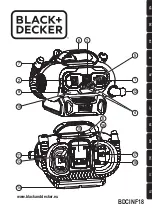
Содержание VRJ
Страница 2: ......