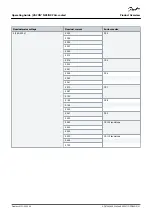
Code
Description
SSS
The hardware changes:
•
The supply, the first letter (Xxx):
-
S = 6-pulse connection (FR4 to FR11)
-
B = Additional DC-connection (FR8 to FR11)
-
O = Standard and input switch (Standalone)
-
J = FR10 to 11 stand-alone with main switch and DC-link terminals
-
P = Standard and input swithc UL (Standalone)
-
K = DC link connectors and input switch UL (Standalone)
•
The mounting, the second letter: (xXx):
-
S = Air-cooled drive
•
The boards, the third letter (xxX):
-
S = Standard boards (FR4 to FR8)
-
V = Coated boards (FR4 to FR8)
-
F = Standard boards (FR9 to FR11)
-
G = Coated boards (FR9 to FR11)
-
A = Fiber, Integrated control (FR10 to FR11 standalone drives)
-
B = Fiber, Integrated control, Coated boards (FR10 to FR11 standalone drives)
-
N = separate IP54 (UL Type 12) control box, standard boards, fiber connection (FR9 IP00, ≥ FR10)
-
O = separate IP54 (UL Type 12) control box, coated boards, fiber connection (FR9 IP00, ≥ FR10)
-
X = separate IP00 control box, standard boards (FR9 IP00)
-
Y = separate IP00 control box, coated boards (FR9 IP00)
A1A2C30000
The option boards. 2 characters for each slot. 00 = the slot is not used
The option board abbreviations:
•
A = basic I/O board
•
B = expander I/O board
•
C = fieldbus board
•
D = special board
•
E = fieldbus board
For example, C3 = PROFIBUS DP
+DNOT
The optional codes. See full list of option codes in the VACON
®
NXP Selection Guide.
1
A brake resistor is available as an option for external installation for 208–240 V (FR7–FR11), 380–500 V (FR7–FR11), and 525–690 V (all enclosure sizes).
3.5 Enclosure Sizes
Example:
The codes for nominal current and nominal mains voltage are part of the type code (see
3.4 Description of the Type Code
) on the
). Use these values to find out the enclosure size of the AC drive from the table.
Product Overview
Operating Guide | VACON® NXS/NXP Air-cooled
AQ275638903263en-000301 / DPD00910| 19
Danfoss A/S © 2020.02


