


MCO 305 Design Guide
__ Software Reference __
MG.33.L4.02 – VLT
®
is a registered Danfoss trademark
95
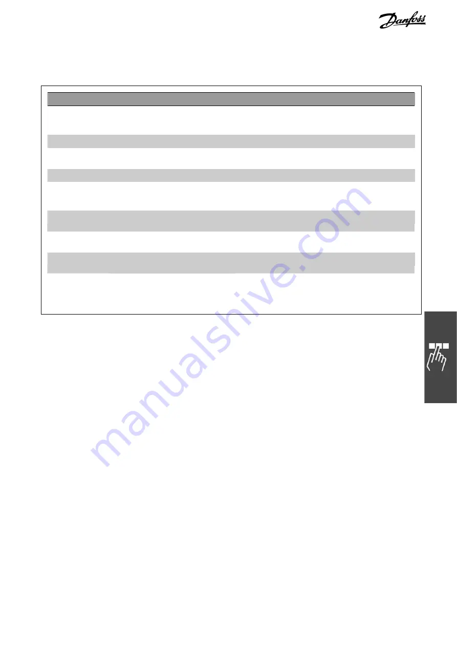
CAM Commands
Commands for the synchronization in CAM-Mode (CAM control).
Command
Description
Syntax
Parameter
CURVEPOS
Retrieve
slave curve position that
corresponds to the current master
position of the curve
res = CURVEPOS
–
DEFMCPOS
define initial position of the master
DEFMCPOS p
p = position in MU
POSA CURVEPOS
move slave to the curve position
corresponding to the master position
POSA CURVEPOS
–
SETCURVE
set CAM curve
SETCURVE array
array = array or curve name
SYNCC
synchronization in CAM-Mode
SYNCC num
num = number of curves to be
processed (0 = drives
remains in CAM mode)
SYNCCMM
synchronization in CAM-Mode with
master marker correction
SYNCCMM num
as above
SYNCCMS
synchronization in CAM-Mode with
slave marker correction
SYNCCMS num
as above
SYNCCSTART
start slave for synchronization in CAM-
Mode
SYNCCSTART pnum
pnum = start stop points number
SYNCCSTOP
stop slave after the CAM
synchronization
SYNCCSTOP pnum
slavepos
pnum = start stop points number
slavepos = slave position after
disengaging
Содержание MCO 305
Страница 4: ......