


23
The calculation is based on PVC or XLPE insulated cables
with copper or aluminium core. A maximum ambient
temperature of 40°C has been taken into account. The given
wire length limits the voltage drop to < 5%.
IMPORTANT: Before connection of the main power cables (L1
- L2 - L3) on the terminal block, it is imperative to check the
correct order of the 3 phases before proceeding to the
connection on then terminal block or the main disconnect/
isolator switch.
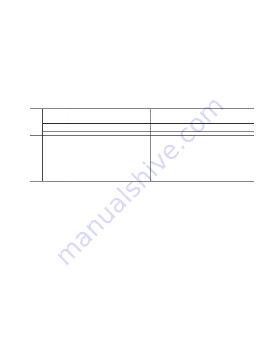
6.4.2 - On-site control wiring
Selection of minimum and maximum wire sections for connection to BW10 units
BW10
Max. connectable
section*
Calculation favourable case:
Suspended aerial lines (standardised routing No. 17)
PVC insulated cable
Calculation unfavourable case:
Conductors in conduits or multi-conductor cables in closed conduit
(standardised routing No. 41)
PVC insulated cable, if possible
Section
Section**
Max. length for
voltage drop <5%
Cable type
Section**
Max. length for voltage drop
<5%
Cable type***
mm² (per phase)
mm² (per phase)
m
mm² (per phase)
m
20
1 x 35
1 x 2.5
60
PVC Cu
1 x 4
100
PVC Cu
25
1 x 35
1 x 2.5
60
PVC Cu
1 x 4
100
PVC Cu
30
1 x 35
1 x 4
80
PVC Cu
1 x 6
120
PVC Cu
35
1 x 35
1 x 4
80
PVC Cu
1 x 6
120
PVC Cu
40
1 x 35
1 x 6
100
PVC Cu
1 x 10
150
PVC Cu
45
1 x 35
1 x 6
100
PVC Cu
1 x 10
150
PVC Cu
50
1 x 35
1 x 10
120
PVC Cu
1 x 16
180
PVC Cu
60
1 x 35
1 x 10
120
PVC Cu
1 x 16
180
PVC Cu
70
1 x 35
1 x 16
140
PVC Cu
1 x 25
205
PVC Cu
80
1 x 35
1 x 16
140
PVC Cu
1 x 25
205
PVC Cu
90
1 x 35
1 x 25
170
PVC Cu
1 x 35
225
PVC Cu
6.4.1 - Field control wiring
Refer to the BW10 Control manual and the certified wiring
diagram supplied with the unit for the field control wiring of
the following features:
•
Remote on/off switch
•
Remote heat/cool switch
•
Demand limit external switch 1
•
Remote dual set point
•
Alarm report
•
Pump control - unit without hydronic module.
•
Relief boiler or electric heater
•
Valve control (refer to the description of options 153 and 154
in the BW10 Control manual)
7 - WATER CONNECTIONS
For size and position of the heat exchanger water inlet and
outlet connections refer to the certified dimensional drawings
supplied with the unit. The water pipes must not transmit any
radial or axial force to the heat exchangers nor any vibration.
The water supply must be analysed and appropriate filtering,
treatment, control devices, isolation and bleed valves and
circuits built in, to prevent corrosion, fouling and deteriora-tion
of the pump fittings. Consult either a water treatment specialist
or appropriate literature on the subject.
7.1 - Operating precautions
The water circuit should be designed to have the least number
of elbows and horizontal pipe runs at different levels. Below the
main points to be checked for the connection:
•
Comply with the water inlet and outlet connections shown
on the unit.
•
Install manual or automatic air purge valves at all high
points in the circuit(s).
•
Use a pressure reducer to maintain pressure in the
circuit(s) and install a safety valve as well as an expan-sion
tank. Units with hydronic module include the safety valve
and expansion tank.
•
Install drain connections at all low points to allow the
whole circuit to be drained.
•
Install stop valves, close to the entering and leaving water
connections.
•
Use flexible connections to reduce the transmission of
vibrations.
•
If the insulation provided is not sufficient, insulate the
cold-water piping, after testing for leaks, both to reduce
heat loss and to prevent condensation.
•
Cover the insulation with a vapour barrier. If the external
water piping to the unit is in an area where the ambient
temperature can fall below 0°C, it should be insulated and
an electric heater should be installed on the piping.
NOTE: For units without hydronic module a screen filter
must be installed as close as possible to the heat exchanger and
in a position that is easily accessible for removal and
cleaning. Units with a hydronic module are equipped with this
filter.
The mesh size of the filter must be 1.2 mm. If this filter is not
installed, the plate heat exchanger can quickly become
contaminated at the first start-up, as it takes on the filter
function, and correct unit operation is affected (reduced
water flow due to increased pressure drop).
Before the system start-up verify that the water circuits are
connected to the appropriate heat exchangers (e.g. no reversal
between evaporator and condenser).
Содержание BW10 020-090
Страница 30: ...30...
Страница 42: ...VMGFT102...


