


Installation manual for DM700 ECDIS
Copyright Danelec Marine A/S
MAN11805-10
Page 24/67
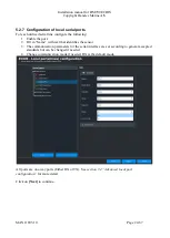
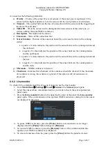
5.2.7 Configuration of local serial ports
For each utilized serial line configure the following:
1.
Enable the port.
2.
Fill in “Name” with text that identifies the sensor.
3.
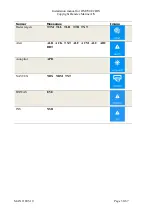
The communication parameters for the serial interface are set according to general accepted
standards but can be changed if needed.
4.
Change communication mode if needed. RX is the default mode.
All ports are one-way ports (Either RX or TX). See
section 7.4 “Advanced local port
for more detail.
Click on
[Next]
to continue.
Содержание DM700 ECDIS
Страница 61: ...Installation manual for DM700 ECDIS Copyright Danelec Marine A S MAN11805 10 Page 61 67...
Страница 63: ...Installation manual for DM700 ECDIS Copyright Danelec Marine A S MAN11805 10 Page 63 67...
Страница 65: ...Installation manual for DM700 ECDIS Copyright Danelec Marine A S MAN11805 10 Page 65 67...
Страница 66: ...Installation manual for DM700 ECDIS Copyright Danelec Marine A S MAN11805 10 Page 66 67...
Страница 67: ...Installation manual for DM700 ECDIS Copyright Danelec Marine A S MAN11805 10 Page 67 67...


