background image


Piranha HN RoHS User Manual 

03-032-20135-00 


Teledyne DALSA 

42 

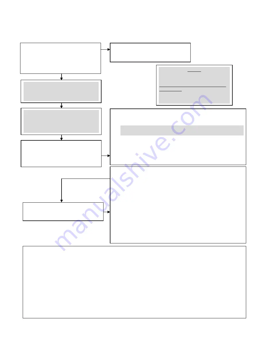
How to Perform Flat Field Correction 


Setup the camera operating environment (ie. 

Line rate, CCD Shift Direction, exposure, offset, 

gain, etc) 


Select the User Set (

ssn


1

,

 2

,

 3 

or

 4


Digital Offset and gain. Background subtract 

values should be set to zero. (

ssb 0

sab 0

ssg 0

)  


Set the calibration sample size using the 

command 

css

. (Optional, since the camera 

defaults to 4096) 


Set the region of interest (

roi

) to include all of 

the images pixels of importance using the 

command 

roi x1 y1 x2 y2


Perform FPN correction. FPN correction should 

be performed before PRNU correction. 

Repeat FPN correction when a temperature change greater then 10°C occurs OR 

when there is a significant change in integration time or gain. 

1.


Stop all light from entering the camera. (Tip: cover lens with a lens cap) 

2.


Verify the output signal level is at dark by issuing the command 

gl

 or 

gla

 (or by viewing a line profile/histogram of the output.) 

3.


Issue the command 

ccf

. The camera will respond with OK> if no errors 

occur. FPN correction automatically calibrates the FPN coefficients. 

4.


After the correction is complete, save the settings by issuing a 

wfc


command. (Note that Forward and Reverse direction settings are stored 
separately and coefficients must be saved before switching directions) 


Perform PRNU correction 

Perform PRNU correction next to determine the multiplication factors (and 

automatic gain settings for each tap) required to bring each pixel to the required 

value (balance target) for a flat white output. 


1.


Place a white reference in front of the camera. (remove lens cap if needed) 

2.


Issue the command 

cpa 2 i

 (or 

cpa 4 i

 if using 

roi

), where I is 

equal to or greater than the maximum pixel value in the image. The 
camera will respond with OK> if no errors occur. 

3.


After the correction is complete, save the settings by issuing a 

wpc


command. (Note that Forward and Reverse direction settings are stored 
separately and coefficients must be saved before switching directions) 

4.


Enable the coefficients using the command 

epc 1 1

. You should now 

see a flat line. (It may be necessary to average many lines to see the 
residual FPN and PRNU.) 

5.


Issue the command 

wus

 to save all User Settings. 

A few notes: 

A.


Repeat the above steps 3-5 for any CCD shift direction change. (i.e. if the above was performed in FORWARD direction, repeat for 
REVERSE direction. 

B.


Always ensure what User Set (

ssn 1

,

 ssn 2

,

 ssn 3

,

 ssn 4

) you are in when performing calibration. When the 

wfc

,

 wpc


and

 wus

 commands are performed, this saves all FPN and  PRNU coefficients and User settings into that set. 

a.


The last User Set (

ssn)

 used in the camera will be the same set loaded into the camera during a power cycle. 

b.


You can view what User Set you are in via the GCP screen. 

c.


Set 0, 

ssn 0

 is the factory calibration set. It cannot be overwritten by the User. 

C.


Remember that the 

cpa

 integer “I” is in 14 bit format. (To set an 8 bit value, multiply this by 64 to get the proper 14 bit value.) (For 

example if the camera is in 8 bit mode and you want a target value of 200DN, the “I” integer for CPA would be 200x64=12800. So, 
sending 

cpa 2 12800

 would give you a target value of 200DN.) 

D.


The 

CPA

 command will automatically adjust all tap gain values. The new gains will be displayed in the GCP screen. (ie. If you 

selected a gain of 5, 

sg 0 5

 before performing the 

CPA 2

 command, depending on the automatic gain adjustment, this value 

may now be different.) 

NOTE: 

Items highlighted in GREY are not necessary 

to perform, unless you require doing so. 

Steps 1, 4 and 5 are usually only needed to 

be performed. 

Содержание Piranha HN HN-80-08k40-R

Страница 1: ...Piranha HN Camera User s Manual HN 80 08k40 xx R High Sensitivity Line Scan CCD Camera with Enhanced QE in Near Infrared 18 August 2012 03 032 20135 00 www teledynedalsa com...

Страница 2: ...te at www teledyne com Teledyne DALSA a Teledyne Technologies company is an international leader in high performance digital imaging and semiconductors with approximately 1 000 employees worldwide hea...

Страница 3: ...__________________________ 15 Lens Mounts 16 Optical Interface 16 Illumination 16 Light Sources 16 Filters 16 Lens Modeling 16 4 Software Interface How to Control the Camera___________________________...

Страница 4: ...1 Temperature Measurement 52 Voltage Measurement 52 Camera Frequency Measurement 52 Returning Camera Settings 52 Returning All Camera Settings with the Camera Parameter Screen 52 Returning Camera Sett...

Страница 5: ...imaging regions for remarkable user controlled sensitivity RoHS and CE compliant Programmability Serial interface ASCII 115 200 baud through Camera Link Programmable gain offset frame and frame rates...

Страница 6: ...performance document scanning Large web inspection Low light applications Note Throughout the manual the cameras are referred to as the Piranha HN xx camera family unless a section is valid to a speci...

Страница 7: ...20 dB Calibration Time 4 3 seconds Performance Gain 0 dB Gain 10 dB Gain 20 dB Min Typ Max Min Typ Max Min Typ Max Dynamic Range TBD TBD TBD TBD TB D TBD Random Noise DN rms TBD TBD TBD TBD TBD TBD SE...

Страница 8: ...ft direction Readout direction is controlled by the software command scd Figure 1 16 Tap Sensor Block Diagram HN 80 08k40 16 STG 64 STG 128 STG 192 STG 240 STG 256 STG 2F 3F 4F 5F 6F 7F 9F 1F Forward...

Страница 9: ...35 00 9 Responsivity Figure 2 Responsivity 0 10 20 30 40 50 60 70 0 200 400 600 800 1000 1200 1400 1600 1800 400 500 600 700 800 900 1000 1100 QE Responsivity DN nJ cm2 Optical Wavelength nm HS 8K Res...

Страница 10: ...ior to installation Do not use damaged cables or connectors or the camera may be damaged 6 Connect Camera Link and power cables 7 After connecting cables apply power to the camera 8 Check the diagnost...

Страница 11: ...ion is active the LED indicates the condition with the highest priority Error and warning states are accompanied by corresponding messages further describing the current camera status Table 2 Diagnost...

Страница 12: ...igh quality linear supplies to minimize noise Use an isolated type power supply to prevent LVDS common mode range violation Note Camera performance specifications are not guaranteed if your power supp...

Страница 13: ...Y0 PAIR1 2 25 X0 15 12 Y0 PAIR1 15 12 X0 3 24 Y1 PAIR2 3 24 X1 16 11 Y1 PAIR2 16 11 X1 4 23 Y2 PAIR3 4 23 X2 17 10 Y2 PAIR3 17 10 X2 5 22 Yclk PAIR4 5 22 Xclk 18 9 Yclk PAIR4 18 9 Xclk 6 21 Y3 PAIR5...

Страница 14: ...to set frame times exposure times and camera modes Direction Control You control the CCD shift direction through the serial interface With the software command scd you determine whether the direction...

Страница 15: ...Piranha HN RoHS User Manual Teledyne DALSA 03 032 20135 00 15 3 Mechanical Interface Figure 6 Piranha HN xx Mechanical Dimensions...

Страница 16: ...life span they produce less light This aging may not be uniform a light source may produce progressively less light in some areas of the spectrum but not others Filters In visible light applications C...

Страница 17: ...Piranha HN RoHS User Manual Teledyne DALSA 03 032 20135 00 17 Figure 7 Primary Points in a Lens System...

Страница 18: ...dyne DALSA cameras Do not assume that the Piranha HN commands perform similarly to older cameras Serial Protocol Defaults 8 data bits 1 stop bit No parity No flow control 115 200 kbps fixed Camera doe...

Страница 19: ...ngs The camera configuration command help screen lists all commands available Parameter ranges displayed are the extreme ranges available Depending on the current camera operating conditions you may n...

Страница 20: ...ode i 0 1 sot set output throughput m 160 320 spc set prnu coeff xi 1 8192 0 61438 spr set prnu range xxi 1 8192 1 8192 0 61438 ssb set subtract background i 0 4096 ssf set sync frequency f 1 34246 ss...

Страница 21: ...6 ssf set sync frequency f 1 130 ssg set system gain i 0 61438 ssn set set number i 0 4 stg set stage selection m 16 64 128 192 240 256 svm set video mode i 0 4 tdi set tdi area mode i 0 1 ugr update...

Страница 22: ...LSA 22 ccf fpn calibration cpa 2 16000 prnu calibrated to an average pixel value of 4000 Command Categories The following diagram categorizes and lists all of the camera s commands This chapter is org...

Страница 23: ...r cosmetic specifications for Area Mode of operation are neither tested nor guaranteed Purpose Selects the camera s operating mode Area Mode is useful for aligning and focusing your camera Syntax tdi...

Страница 24: ...amera Link control CC3 CC3 1 forward CC3 0 reverse Available only in TDI Mode Notes The following user settings are stored separately for forward and reverse direction digital gain system gain backgro...

Страница 25: ...ccd pixel and with a 0 5 x magnification the object pixel size is 14x14 um In other words the smallest feature that the CDD can distinguish is 14 um In this system the shaft encoder should be configur...

Страница 26: ...s 4 to 9 and horizontal binning is set to 2 Because pixel 3 is now included in the same data group as pixel 4 the region of interest will now include the data from pixel 3 Also pixel 10 is included in...

Страница 27: ...nning values Increasing the vertical binning decreases the maximum allowable line rate For internal exposure mode sem 7 the frame is clipped to the maximum allowable and the camera sends a warning For...

Страница 28: ...f to set the line frame rate Setting the Exposure Mode Purpose Sets the camera s exposure mode allowing you to control your sync and line frame rate generation Syntax sem m Syntax Elements m Exposure...

Страница 29: ...xternal Trigger Maximum Exposure Time Figure 12 Mode 3 Timing Mode 7 Internal Frame Rate Maximum Exposure Time In this mode the frame rate is set internally using the ssf command with a maximum exposu...

Страница 30: ...Camera Link mode and number of CCD integration stages Notes If you enter a frame rate frequency outside of the range displayed on the help screen an error message is returned and the frame rate remain...

Страница 31: ...1 2 4 User SBV 1 2 4 User SDV 1 2 4 User TDI 0 1 User STG 16 64 128 192 240 256 CL_Taps If User CLM 2 3 then CL_Taps 2 If User CLM 15 16 then CL_Taps 4 If User CLM 21 then CL_Taps 8 Hor_Bin User SBH...

Страница 32: ...the camera s output rate These two commands work together to determine your final camera output configuration You can further configure your readout using the smm command to select the camera s pixel...

Страница 33: ...191 CL tap 2 2 4 to 8192 smm 1 CL tap 1 8192 8190 to 2 CL tap 2 8191 8189 to 1 sot 80 40 MHz strobe sot 160 80 MHz strobe clm 15 Medium 4 Camera Link taps where 1 Every 2nd Odd Pixel 2 Every 2nd Even...

Страница 34: ...3 Every 4th Odd Pixel 4 Every 4th Even Pixel 1 Every 4th Odd Pixel 2 Every 4th Even Pixel 3 Every 4th Odd Pixel 4 Every 4th Even Pixel 8 smm 0 CL tap 1 1 9 to 8185 CL tap 2 2 10 to 8186 CL tap 3 3 11...

Страница 35: ...ain the current Camera Link mode use the command gcp or get clm The bit patterns are defined by the Teledyne DALSA Camera Link Roadmap available here Teledyne DALSA application notes Related Commands...

Страница 36: ...mand gcp or get smm This command is available in both TDI and Area Mode Refer to the following figures and tables for an explanation of pixel readout and mirror direction Refer to Image Sensor for sen...

Страница 37: ...ixel is rounded up to the end of the binned area In Area Mode the roi must be within the stage If the requested roi is above the stage the roi rows will be clipped The start and end rows will be clipp...

Страница 38: ...U coefficients are multipliers and are defined to be of a value greater than or equal to 1 This ensures that all pixels will saturate together When using PRNU correction it is important that the A D o...

Страница 39: ...st 16 pixels of tap 8 This seam matching continues to tap 1 For adjacent tap 9 the mean of the first 16 pixels are gained to match the mean of the last 16 pixels of tap 8 This seam matching continues...

Страница 40: ...ion determines exactly how much offset to subtract per pixel in order to obtain flat output when the CCD is not exposed The white light calibration is performed next to determine the multiplication fa...

Страница 41: ...ipped flat field correction results may be inaccurate 6 Correction results are valid only for the current stage selection If you change the number of stages it is recommended that you recalculate your...

Страница 42: ...s equal to or greater than the maximum pixel value in the image The camera will respond with OK if no errors occur 3 After the correction is complete save the settings by issuing a wpc command Note th...

Страница 43: ...fficient Purpose Sets an individual pixel s FPN coefficient Syntax sfc x i Syntax Elements x The pixel number from 1 to sensor pixel count i Coefficient value in a range from 0 511 12 bit LSB Notes Av...

Страница 44: ...FPN before calibrating PRNU If you are not performing FPN calibration then issue the rpc reset pixel coefficients command Example cpa 2 16000 Setting a Pixel s PRNU Coefficient Purpose Sets an indivi...

Страница 45: ...the this command to correct for this where Syntax ssg i Syntax Elements i Gain setting The gain ranges are 0 to 61438 The digital video values are multiplied by this value where Notes Use this command...

Страница 46: ...ng the user settings save command wus settings are saved depending on which mode the camera is operating in when the command is issued Also when operating in TDI Mode analog gain and offset digital ga...

Страница 47: ...our camera These settings are stored in the camera s volatile memory and will not be restored once you power down your camera To save these settings for reuse at power up use the command wus Settings...

Страница 48: ...et Number Purpose When saving and loading camera settings you have a choice of saving up to four different sets and loading from five different sets four user and one factory This command determines t...

Страница 49: ...t direction Syntax wpc Notes Available in TDI mode only Available only when operating the camera in internal direction control scd 0 or 1 Example wpc Saving the Current FPN Coefficients Purpose Saves...

Страница 50: ...1024 24 24 Where i 1 to 8192 Svm 2 Horizontal HORi Modulus DCi Modulus Modulus i 1 1024 256 256 Where i 1 to 8192 Svm 3 Vertical VERi Modulus DCi FR 256 FR 1 2 3 4 256 Svm 4 Diagonal DIAGi Modulus HO...

Страница 51: ...NU coefficients are not included in the data Values returned are in 12 bit DN Available in TDI Mode only Related Commands roi Example gl 10 20 Returning Averaged Lines of Video Setting the Number of L...

Страница 52: ...rebooted using the command rc or can be powered down manually You will have to correct the temperature problem or the camera will shut down again Voltage Measurement The command vv displays the camer...

Страница 53: ...t line rate Value is set with the ssf command CCD Direction internal forward CCD shift direction set with the scd command Mirroring Mode 0 left to right Readout direction set with the smm command Anal...

Страница 54: ...ound Subtract 0 Background subtract settings set with the ssb command Returning Camera Settings with Get Commands You can also return individual camera settings by inserting a get in front of the comm...

Страница 55: ...d command E g requesting exposure time longer than line time automatically adjusts the line time to meet the exposure time requirement Warning 07 Coefficient may be inaccurate A D clipping has occurre...

Страница 56: ...communication error or a bad file was sent Commands Quick Reference As a quick reference the following table lists all of the camera configuration commands available to the camera user For detailed in...

Страница 57: ...umber get camera parameters gcp Reads all of the camera parameters get camera serial gcs Read the camera serial number get camera version gcv Displays the firmware version and FPGA version get values...

Страница 58: ...only in TDI Mode set digital binning horizontal sdh m Sets the horizontal binning value Available values are 1 2 4 set digital binning vertical sdv m Sets the vertical binning value Available values...

Страница 59: ...i set number in a range from 0 to 4 stage select stg i Sets the number of stages Allowable values are 16 64 128 192 240 256 set video mode svm i Switch between normal video mode and test patterns 0 v...

Страница 60: ...6kV CD 8kV AD 1995 EN 61000 4 3 3V m 1996 EN 61000 4 4 500V 1100V 1995 This product complies with the requirements of the Low Voltage Directive 73 23 EEC and the EMC Directive 89 336 EEC and carries...

Страница 61: ...st can obscure pixels producing dark patches on the sensor response Dust is most visible when the illumination is collimated The dark patches shift position as the angle of illumination changes Dust i...

Страница 62: ...can scratch the window The Anticon Gold 9 x 9 wiper made by Milliken is both ESD safe and suitable for class 100 environments Another ESD acceptable wiper is the TX4025 from Texwipe 4 An alternative...

Страница 63: ...Piranha HN RoHS User Manual Teledyne DALSA 03 032 20135 00 63 Revision History Revision Number Change Description Date 00 Revised Preliminary Version for Consignment Cameras August 18 2012...

Страница 64: ...meters 18 commands 22 list 56 connectors 10 D data bus 14 data rate 7 digital signal processing 44 direction externally controlled 24 web movement 24 DVAL 14 E EMC Declaration of Conformity 60 error m...

Страница 65: ...ines 12 supply 12 R readout configuring 32 direction 36 rebooting 50 resolution 6 responsivity 7 Revision History 63 roi 37 S SEE 7 sensitivity level 23 sensor 8 cleaning 61 serial interface 18 defaul...

Отзывы: