IOM 1210-7 • MAGNITUDE
®
MODEL WMC CHILLERS
6
www.DaikinApplied.com
I
nsTallaTIon
I
nsTallaTIon
Nameplates
There are several identification nameplates on the chiller:
• The unit nameplate is located on the exterior of the Unit
Control Panel. Both the Model No. and Serial No. are
located on the unit nameplate; the Serial No. is unique to
the unit. These numbers should be used to identify the
unit for service, parts, or warranty questions. This plate
also has the unit refrigerant charge and electrical ratings.
• Vessel nameplates are located on the evaporator and
condenser. They have a National Board Number (NB)
and a serial number, either of which identify the vessel
(but not the entire unit).
Receiving and Handling
The unit should be inspected immediately after receipt for
possible damage. All Daikin Applied centrifugal water chillers
are shipped FOB factory and all claims for handling and
shipping damage are the responsibility of the consignee.
On units with factory-installed insulation, the insulation
is removed from the vessel lifting hole (also used for
transportation tie-downs) locations and is shipped loose. It
should be secured in place after the unit is finally placed.
Neoprene vibration isolation pads are shipped loose in the
power panel. If the unit is equipped with a shipping skid, leave
the skid in place until the unit is in its final position. This will aid
in handling the equipment.
CAUTION
Extreme care must be used when rigging the unit to prevent
damage to the control panels and refrigerant piping. See the
certified dimension drawings included in the job submittal for
the weights and center of gravity of the unit. If the drawings
are not available, consult the local Daikin Applied sales office
for assistance.
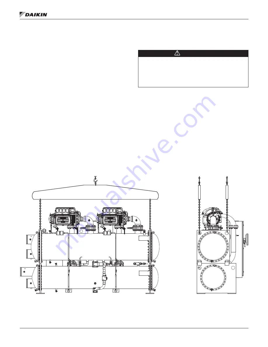
The unit can be lifted by fastening the rigging hooks to the four
corners of the unit where the rigging eyes are located — see
. A spreader bar must be used between the rigging
lines to prevent damage to the control panels, piping, and
electrical panels. The spreader-bar length should be equal
to, or no more than 1-foot shorter than, the distance between
the lifting holes located at opposite ends of the chiller. The
unit will require a single spreader-bar of this length capable
of supporting 1.5 times the shipping weight of the unit.
Separately, all cables and hooks by themselves must also be
capable of supporting 1.5 times the shipping weight of the unit.
If a knockdown option was ordered on the unit, reference the
information.
Figure 5: WMC Unit Rigging
NOTE:
The spreader bars in
are a representation only and may not reflect the appearance of the actual spreader bars
needed.
LEFT VIEW
REAR VIEW
Содержание Magnitude
Страница 4: ......
Страница 23: ...Installation www DaikinApplied com 21 IOM 1210 7 MAGNITUDE MODEL WMC CHILLERS...
Страница 24: ...IOM 1210 7 MAGNITUDE MODEL WMC CHILLERS 22 www DaikinApplied com Installation Figure 20 Wiring Index...
Страница 25: ...Installation www DaikinApplied com 23 IOM 1210 7 MAGNITUDE MODEL WMC CHILLERS...
Страница 26: ...IOM 1210 7 MAGNITUDE MODEL WMC CHILLERS 24 www DaikinApplied com Installation Figure 21 Controller Box Wiring...


