www.DaikinApplied.com 57
IOM 1210-7 • MAGNITUDE
®
MODEL WMC CHILLERS
o
peraTIon
Events
Events do not generate a warning message to the operator but they may notify the BAS, if used. Chiller operation may be affected
by events.
Table 23:
Unit Events
Description
HMI Alarm Message
Alarm Reset
High Motor Current On Compressor #1
No Alert shown on HMI panel
No Alarm
High Motor Current On Compressor #2
No Alert shown on HMI panel
No Alarm
Evaporator Freeze Protect Comp 1
EVAP PUMP ON - Suction pressure Low (Freeze)
Auto-clears
Evaporator Freeze Protect Comp 2
EVAP PUMP ON - Suction pressure Low (Freeze)
Auto-clears
Evaporator Pump #1 Fault
No Alert shown on HMI panel
No Alarm
Evaporator Pump #2 Fault
No Alert shown on HMI panel
No Alarm
Re-Start Fault
No Alert shown on HMI panel
No Alarm
Re-Start Fault Comp 1
No Alert shown on HMI panel
No Alarm
Re-Start Fault Comp 2
No Alert shown on HMI panel
No Alarm
Table 24:
Compressor Events
Description
HMI Alarm Message
Alarm Reset
Bearing Fault 1
COMPR STOP - Compressor Fault
Auto-clears
Pauses 20 min after 3rd alarm in 50 min
Bearing Fault 2
COMPR STOP - Compressor Fault
Auto-clears
Pauses 20 min after 3rd alarm in 50 min
Motor Fault 1
COMPR STOP - Compressor Fault
Auto-clears
Pauses 20 min after 3rd alarm in 50 min
Motor Fault 2
COMPR STOP - Compressor Fault
Auto-clears
Pauses 20 min after 3rd alarm in 50 min
Drive Fault 1
COMPR STOP - Compressor Fault
Auto-clears
Drive Fault 2
COMPR STOP - Compressor Fault
Auto-clears
Internal Control Fault 1
COMPR STOP - Compressor Fault
Auto-clears
Internal Control Fault 2
COMPR STOP - Compressor Fault
Auto-clears
The Controller
The controller is located in the control panel (see
).
Unit, compressor, evaporator, and condenser information is
viewable on it, and all setpoints can be accessed from it. It
is encouraged to use the controller to change setpoints only
when the HMI is unavailable. The controller LCD screens
read only in IP units of measure (inch-pounds and degrees
Fahrenheit). SI units of measure can be selected with the
appropriate controller setpoint screen but will appear only on
the HMI.
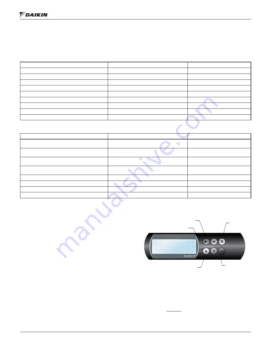
Keypad
A 4-line by 20-character/line liquid crystal display and 6-button
keypad is mounted on the controller, as shown in
.
Figure 60: Controller Keypad
The four arrow keys (UP, DOWN, LEFT, RIGHT) have three
modes of use:
1. Select a specific data screen in the menu matrix using
dynamic labels such as ALARM, VIEW, SET, etc. This
mode is entered by pressing the MENU key.
For ease
of use, a pathway connects the appropriate button to its
respective label on the screen.
.
E
I
V
M
R
A
L
A
<
<
<
T
E
S
W
MENU Key
Key-to-Screen Pathway
Red Alarm Light Behind
ARROW Keys (4)
ENTER Key with
Green Run Light
Behind
N
O
I
S
S
I
M
O
C
<
M
Содержание Magnitude
Страница 4: ......
Страница 23: ...Installation www DaikinApplied com 21 IOM 1210 7 MAGNITUDE MODEL WMC CHILLERS...
Страница 24: ...IOM 1210 7 MAGNITUDE MODEL WMC CHILLERS 22 www DaikinApplied com Installation Figure 20 Wiring Index...
Страница 25: ...Installation www DaikinApplied com 23 IOM 1210 7 MAGNITUDE MODEL WMC CHILLERS...
Страница 26: ...IOM 1210 7 MAGNITUDE MODEL WMC CHILLERS 24 www DaikinApplied com Installation Figure 21 Controller Box Wiring...


