D-EOMHP01501-22_00EN 13/29
3.7.
Network Control
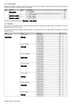
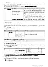
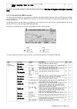
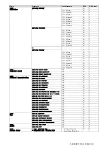
To allow unit’s control from BMS system the Control Source parameter [4.00] needs to be set in Network. All settings related to
BSM control communication can be visualized in Page [4]:
Menu Parameter
Range
Description
R/W
04
00
(
Control Source
)
0-1
0 = Network control disabled
On/Off command from network
W
1 = Network control enabled
01
(
Enable
)
0-1
0 = Unit is Enable
On/Off command from network visualization
R
1 = Unit is Disabled
02
(
Cool LWT
)
0..30°C
-
Cooling water temperature setpoint from network R
03
(
Heat LWT
)
30..60°C -
Heating water temperature setpoint from network R
04
(
Mode
)
CH/HP
-
Operating mode from network
R
Refer to communication protocol documentation for specific registers addresses and the related read/write access level.
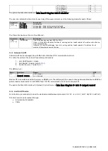
The path in the Web HMI interface is
“
Main Menu à View/Set Unit à Network Control
”.
3.8.
Thermostatic Control
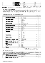
Thermostatic control settings allow to set up the response to temperature variations. Default settings are valid for most application,
however plant specific conditions may require adjustments to have a smooth control or a quicker response of the unit.
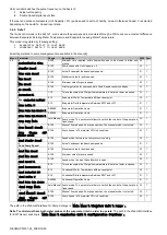
The unit controller will start the first compressor if the controlled temperature is higher (Cool Mode) or lower (Heat Mode) than the
active setpoint of at least a Start Up DT value, whereas second compressor when available is started if the controlled temperature
is higher (Cool Mode) or lower (Heat Mode) than the active setpoint (AS) of at least a Stage Up DT (SU) value. Compressors stop
if performed following same procedure looking to the parameters Stage Down DT and Shut Down DT.
Cool Mode
Heat Mode
First compressor start
Controlled Temperature > Se
Start Up DT
Controlled Temperature < Setpoint -
Start Up DT
Other compressors start
Controlled Temperature > Se
Stage Up DT
Controlled Temperature < Setpoint -
Stage Up DT
Last compressor stop
Controlled Temperature < Setpoint -
Shut Dn DT
Controlled Temperature > Se
Shut Dn DT
Other compressors stop
Controlled Temperature < Setpoint -
Stage Dn DT
Controlled Temperature > Se
Stage Dn DT
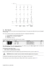
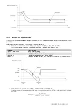
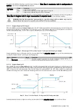
A qualitative example of compressors start-up sequence in cool mode operation is shown in the graph below.
Graph 1
– Compressors start-up sequence - Cool mode
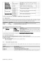
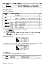
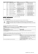
Thermostatic control settings are accessible from menu [9]:
Menu Parameter
Range
Description
R/W
Psw
09
00
(
Start Up DT
)
0-10
Delta temperature respect the active setpoint to start the unit
(startup of first compressor)
W
1
01
(
Shut Down DT
)
0-MIN(5, 60.5-LwtSp)
Delta temperature respect the active setpoint to stop the unit
(shutdown of latest compressor)
W
1
Содержание EWWQ-KC
Страница 28: ...D EOMHP01501 22_00EN 28 29 Notes ...


