


46
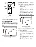
For example, assume the system is an air conditioner
matched with a furnace. With a call for low stage cooling,
the air conditioner will calculate the system’s low stage cool-
ing airflow demand. The air conditioner will then send a fan
request along with the low stage cooling airflow demand to
the furnace. Once received, the furnace will send the low
stage cooling airflow demand to the ECM motor. The ECM
motor then delivers the low stage cooling airflow. See the
applicable ComfortNet air conditioner or heat pump instal-
lation manual for the airflow delivered during cooling or heat
pump heating.
In continuous fan mode, the CTK0* thermostat provides the
airflow demand. The thermostat may be configured for one
of three continuous fan speed settings allow for 25%, 50% or
75% airflow, based on the furnaces’ maximum airflow capa-
bility. During continuous fan operation, the thermostat sends
a fan request along with the continuous fan demand to the
furnace. The furnace, in turn, sends the demand to the
ECM motor. The ECM motor delivers the requested continu-
ous fan airflow.
F
OSSIL
F
UEL
A
PPLICATIONS
This furnace can be used in conjunction with a ComfortNet™
compatible heat pump in a fossil fuel application. A fossil fuel
application refers to a combined gas furnace and heat pump
installation which uses an outdoor temperature sensor to deter-
mine the most cost efficient means of heating (heat pump or
gas furnace). The balance point temperature may be adjusted
via the CTK0* thermostat advanced user menus (see CTK0*
instructions for additional information).
CTK0* W
IRING
NOTE:
Refer to Electrical Connections for 115 volt line connections
to the furnace.
NOTE:
A removable plug connector is provided with the control
to make thermostat wire connections. This plug may be removed,
wire connections made to the plug, and replaced. It is
strongly
recommended that multiple wires into a single terminal be twisted
together prior to inserting into the plug connector. Failure to do
so may result in intermittent operation.
Typical 18 AWG thermostat wire may be used to wire the system
components. One hundred (100) feet is the maximum length of
wire between indoor unit and outdoor unit, or between indoor
unit and thermostat. Wire runs over (100) feet require larger
gauge wire.
F
OUR
-W
IRE
I
NDOOR
AND
O
UTDOOR
W
IRING
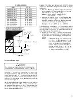
Typical ComfortNet™ wiring will consist of four wires between
the indoor unit and outdoor unit and between the indoor unit and
thermostat. The required wires are: (a) data lines, 1 and 2; (b)
thermostat “R” (24 VAC hot) and “C” (24 VAC common).
T
WO
-W
IRE
O
UTDOOR
, F
OUR
-W
IRE
I
NDOOR
W
IRING
As few as two wires can be utilized between the indoor and
outdoor units. For this wiring scheme, only the data lines, 1 and
2, are needed between the indoor and outdoor units. A 40VA,
208/230 VAC to 24VAC transformer must be installed in the out-
door unit to provide 24VAC power to the outdoor unit’s electronic
control. The transformer is included in selected communicat-
ing thermostat kits. See kit instructions for mounting and wir-
ing instructions. Four wires are required between the indoor
unit and thermostat. If using a communicating thermostat
kit that does not include a transformer in a dual fuel system,
the accessory transformer kit TFK01 should be used.
NOTE:
Use of the accessory transformer is recommended if
installing a dual fuel/fossil fuel system. Failure to use the
transformer in the outdoor unit could result in over loading of the
furnace transformer.
C
OMFORT
N
ET
™ C
OMPATIBLE
F
URNACE
WITH
N
ON
-C
OMFORT
N
ET
COMPATIBLE
S
INGLE
-S
TAGE
A
IR
C
ONDITIONER
Four wires are required between the furnace and thermostat.
Two wires are required between the furnace control and single
stage air conditioner. For this system configuration, the “Y1”
terminal on the integrated furnace control becomes an output
rather than an input. The “Y1” connection to the outdoor unit is
made using both of the 4-position thermostat connectors in the
CTK0* kit. Remove the red keying tabs from the on-board con-
nector block and position both 4-position connector such that
“1”, “2”, “R”, “C”, and “Y1” positions are filled.
C
OMFORT
N
ET
™ S
YSTEM
A
DVANCED
F
EATURES
The ComfortNet system permits access to additional system
information, advanced setup features, and advanced diagnos-
tic/troubleshooting features. These advanced features are
organized into a menu structure. The menus are accessed
and navigated as described in the instructions provided with
the communicating control.
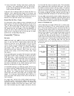
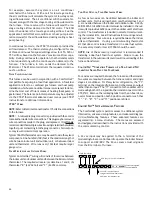
A 24 vac input may be applied to the G terminal of the
modulating furnace control board to operate the indoor blower
to support an HRV/ERV. The 24 vac source must originate
from the R terminal of furnace.
W1 W2 Y1
Y2
O
DEHUM
24 vac "G" input to Furnace
Integrated Control module From
ERV / HRV or Similar Devices
1
1
2
R
C
2
Furnace Integrated
Control Module
R
C
G
CTK0* Thermostat
4-Pin (X2), 7 Pin, or 9 Pin Connector
Содержание DC97MC
Страница 63: ...63 THIS PAGE LEFT INTENTIONALLY BLANK...


