


32
G
AS
P
IPING
C
ONNECTIONS
T
O
AVOID
POSSIBLE
UNSATISFACTORY
OPERATION
OF
EQUIPMENT
DAMAGE
DUE
TO
UNDERFIRING
OR
EQUIPMENT
,
USE
THE
PROPER
SIZE
OF
NATURAL
/
PROPANE
GAS
PIPING
NEEDED
WHEN
RUNNING
PIPE
FROM
THE
METER
/
TANK
TO
THE
FURNACE
.
WARNING
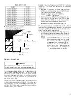
The gas piping supplying the furnace must be properly sized
based on the gas flow required, specific gravity of the gas,
and length of the run. The gas line installation must comply
with local codes, or in their absence, with the latest edition
of the National Fuel Gas Code, NFPA 54/ANSI Z223.1 or CAN/
CSA B149.1-15 in Canada.
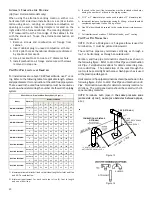
Natural Gas Capacity of Pipe In Cubic Feet of Gas Per Hour (CFH)
Nominal
½
¾
1
1¼
1½
2
2½
Actual ID:
0.622
0.824
1.049
1.380
1.610
2.067
2.469
Length (ft)
10
170
360
678
1390
2090
4020
6400
20
118
247
466
957
1430
2760
4400
30
95
199
374
768
1150
2220
3530
40
81
170
320
657
985
1900
3020
50
72
151
284
583
873
1680
2680
60
65
137
257
528
791
1520
2430
70
60
126
237
486
728
1400
2230
80
56
117
220
452
677
1300
2080
90
52
110
207
424
635
1220
1950
100
50
104
195
400
600
1160
1840
125
44
92
173
355
532
1020
1630
150
40
83
157
322
482
928
1480
175
37
77
144
296
443
854
1360
200
34
71
134
275
412
794
1270
250
30
63
119
244
366
704
1120
Capacity in Cubic Feet of Gas per Hour
This chart refers to natural gas w ith an inlet pressure of less than 2 psi and a
pressure drop of 0.5" W.C. Specific gravity is 0.60.
Pipe Size (in.)
CFH =
BTUH Furnace Input
Heating Valve of Gas (BTU/Cubic Foot)
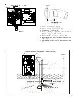
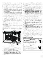
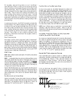
To connect the furnace to the building’s gas piping, the in-
staller must supply a ground joint union, drip leg, manual
shutoff valve, and line and fittings to connect to gas valve. In
some cases, the installer may also need to supply a transition
piece from 1/2" pipe to a larger pipe size.
The following stipulations apply when connecting gas piping.
Refer to
Gas Piping Connections
figure for typical gas line
connections to the furnace.
•
Gas piping must be supported external to the furnace
cabinet so that the weight of the gas line does not
distort the burner rack, manifold or gas valve.
•
Use black iron or steel pipe and fittings for building
piping. Where possible, use new pipe that is properly
chamfered, reamed, and free of burrs and chips. If old
pipe is used, be sure it is clean and free of rust, scale,
burrs, chips, and old pipe joint compound.
•
Use pipe joint compound on male threads ONLY. Always
use pipe joint compound (pipe dope) that is APPROVED
FOR ALL GASES. DO NOT apply compound to the first
two threads.
•
Use ground joint unions.
•
Install a drip leg to trap dirt and moisture before it can
enter the gas valve. The drip leg must be a minimum
of three inches long.
•
A line pressure test port is provided on the gas
valve. If desired, install a 1/8" NPT pipe plug fitting,
accessible for test gage connection, immediately
upstream of the gas supply connection to the furnace.
•
Always use a back-up wrench when making the
connection to the gas valve to keep it from turning.
The orientation of the gas valve on the manifold must
be maintained as shipped from the factory. Maximum
torque for the gas valve connection is 375 in-lbs;
excessive over-tightening may damage the gas valve.
•
Install a manual shutoff valve between the gas meter
and unit within six feet of the unit. If a union is installed,
the union must be downstream of the manual shutoff
valve, between the shutoff valve and the furnace.
•
Tighten all joints securely.
•
Connection method must be in compliance with all
local and national codes. US: National Fuel Gas Code
(NFGC) NFPA 54-2012/ANSI Z223.1-2012 and the
Installation Standards, Warm Air Heating and Air
Conditioning Systems ANSI/NFPA 90B.
In Canada, CANADA: National Standard of Canada,
Natural Gas and Propane Installation Code
(NSCNGPIC) CSA B149.1-15.
Connect the furnace to the building piping by one of the
following methods:
–
Rigid metallic pipe and fittings.
–
Semi-rigid metallic tubing and metallic fittings.
Aluminum alloy tubing must not be used in exterior
locations. In order to seal the grommet cabinet
penetration, rigid pipe must be used to reach the
outside of the cabinet. A semi-rigid connector to
the gas piping may be used from there.
•
Use listed gas appliance connectors in accordance with
their instructions. Connectors must be fully in the same
room as the furnace.
•
Protect connectors and semirigid tubing against physical
and thermal damage when installed. Ensure aluminum-
alloy tubing and connectors are coated to protect
against external corrosion when in contact with masonry,
plaster, or insulation, or subjected to repeated wetting
by liquids such as water (except rain water), detergents,
or sewage.
Содержание DC97MC
Страница 63: ...63 THIS PAGE LEFT INTENTIONALLY BLANK...


