


35
C
IRCULATING
A
IR
& F
ILTERS
D
UCT
WORK
- A
IR
F
LOW
Duct systems and register sizes must be properly designed for
the CFM and external static pressure rating of the furnace.
Design the ductwork in accordance with the recommended
methods of “Air Conditioning Contractors of America” Manual
D.
Install the duct system in accordance with Standards of the
National Board of Fire Underwriters for the Installation of Air
Conditioning, Warm Air Heating and Ventilating Systems. Pam-
phlets No. 90A and 90B.
A closed return duct system must be used, with the return
duct connected to the furnace.
NOTE:
Ductwork must never
be attached to the back of the furnace.
For upflow installa-
tions requiring 1800 CFM or more, use either two side returns
or bottom return or a combination of side and bottom. Flex-
ible joints may be used for supply and return connections to
reduce noise transmission. To prevent the blower from inter-
fering with combustion air or draft when a central return is
used, a connecting duct must be installed between the unit
and the utility room wall. Never use a room, closet, or alcove
as a return air chamber.
C
HECKING
D
UCT
S
TATIC
Refer to your furnace rating plate for the maximum ESP
(external duct static) rating.
Total external static refers to everything external to the
furnace cabinet. Cooling coils, filters, ducts, grilles, reg-
isters must all be considered when reading your total ex-
ternal static pressure. The supply duct pressure must be
read between the furnace and the cooling coil. This read-
ing is usually taken by removing the “A” shaped block off
plate from the end on the coil; drilling a test hole in it and
reinstalling the block off plate. Take a duct static reading
at the test hole. Tape up the test hole after your test is
complete. The negative pressure must be read between
the filter and the furnace blower.
Excessive external static pressure will result in insuffi-
cient air which can cause excessive temperature rise. This
can cause limit switch tripping and heat exchanger fail-
ure.
To determine total external duct static pressure, proceed as
follows;
1. With clean filters in the furnace, use a draft gauge
(inclined manometer) to measure the static pressure
of the return duct at the inlet of the furnace. (Nega-
tive Pressure)
2. Measure the static pressure of the supply duct. (Posi-
tive Pressure)
3. The difference between the two numbers is your total
external static pressure.
Example:
static reading from return duct = -0.1" W.C.
static reading from supply duct = +0.3" W.C.
total external static pressure on this system = 0.4" W.C.
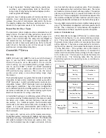
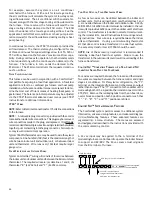
NOTE:
Both readings may be taken simultaneously and
read directly on the manometer if so desired. If an air
conditioner coil or Electronic Air Cleaner is used in con-
junction with the furnace, the readings must also include
these components, as shown in the following drawing.
4. Consult proper tables for the quantity of air.
If the total external static pressure exceeds the maxi-
mum listed on the furnace rating plate, check for closed
dampers, registers, undersized and/or oversized poorly
laid out duct work.
The temperature rise of the furnace must be within the
temperature rise range listed on the furnace rating plate.
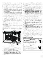
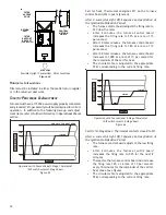
Checking Static Pressure
Figure 41
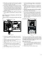
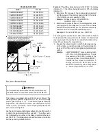
B
OTTOM
R
ETURN
A
IR
O
PENING
[U
PFLOW
M
ODELS
]
The bottom return air opening on upflow models utilizes a
“lance and cut” method to remove sheet metal from the duct
opening in the base pan. To remove, simply press out the
lanced sections by hand to expose the metal strips retaining
the sheet metal over the duct opening. Using tin snips, cut
the metal strips and remove the sheet metal covering the
duct opening. In the corners of the opening, cut the sheet
metal along the scribe lines to free the duct flanges. Using
the scribe line along the duct flange as a guide, bend the duct
flanges around the perimeter of the opening using a pair of
seamer pliers or seamer tongs.
NOTE:
Airflow area will be reduced by approximately 18% if
duct flanges are not folded open. This could cause performance
issues and noise issues.
Содержание DC97MC
Страница 63: ...63 THIS PAGE LEFT INTENTIONALLY BLANK...


