IM 1240-4 • INTELLIGENT EQUIPMENT 12 www.DaikinApplied.com
Installation
Wiring Interconnections
DANGER
Electric shock hazard. Can cause personal injury or equipment
damage.
Prior to installing Intelligent Equipment hardware, power must be removed
from the unit. This means removing power at the breaker panel serving
the unit, and following proper lockout/tagout procedures at said breaker
panel for the duration of the install. Power should not be reapplied until all
electrical interconnections have been made and verified.
This equipment must be properly grounded. Connections and service to
the MicroTech II WMC Water-Cooled chiller, MicroTech III Air cooled Chiller,
Packaged Rooftop, or Outdoor Air Handling Unit Controller, Machine-to-
Machine Gateway and Energy Management Module must be performed
only by personnel knowledgeable in the operation of the equipment being
controlled.
CAUTION
Static sensitive components. Can cause equipment damage.
Discharge any static electrical charge by touching the bare metal inside the
control panel before performing any service work. Never unplug cables,
circuit board terminal blocks, or power plugs while power is applied to the
panel.
WARNING
Care must be taken to ensure a minimum of 5 inches of clearance between
all cables and conductors with 300V-rated insulation or less and areas of the
control enclosure containing higher voltage components and conductors.
NOTICE
In the event that 300V or lower rated cables and conductors cannot be
practically isolated from 600V-rated cables and conductors, a section
of 600V-rated shrink wrap tubing is included in the installation kit. This
tubing can be cut-to-fit and placed over the lower voltage rated cables and
conductors to increase their rating to 600V.
M2M Connection to MTIII
The M2M Gateway is connected to the MicroTech III unit
controller via Ethernet. Connect one end of the provided 6'
Ethernet Patch cable to the M2M port marked, “ETH”, and the
other end to the MicroTech III Unit controller port marked, “TIP”
(
).
Figure 17: ‘ETH’ and ‘TIP’ Ports
M2M Connection to WMC
The M2M Gateway is connected to the WMC-D vintage HMI
PC via Ethernet. Connect one end of the provided 6’ Ethernet
Patch cable to the M2M port marked, “ETH”, and the other end
to the HMI PC port marked, “LAN2” (
M2M Connection to EMM
(Not on Gateway-on-the-Go, IE Express, or
WMC kits)
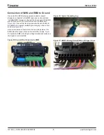
The M2M Gateway is connected to the EMM via USB. Connect
the type-A end of the provided 3' USB cable to the M2M port
marked, “USB1”, and the type-B end of the same cable to the
).
Figure 18: USB Connections
Figure 19: M2M Connection to WMC-D Vintage
Содержание AGZ-D
Страница 45: ......


