


IM 1240-4 • INTELLIGENT EQUIPMENT 10 www.DaikinApplied.com
Installation
Installing Fuse Block
(Not on Gateway-on-the-Go, IE Express, or
WMC kits)
Prior to installing any Intelligent Equipment components, power
must be removed from the unit. Power must be removed at
the breaker panel serving the unit, and proper lockout/tagout
procedures should be followed for the duration of the install.
After removing unit power at the breaker panel, the installer
must verify the absence of power at the unit using a multimeter.
Only if power has been verified absent, should the technician
begin the install. The retrofit kit is shipped with the fuse block
shipped loose. The fuse block must be installed inside the unit
control panel. The installation location will vary depending on
the unit model and size of the control enclosure (see
for correct component locations on AGZ and
AWV models). On AWS models, locate Intelligent Equipment
hardware as space allows within the control enclosure.
provide a typical layout of AWS small and large
enclosures. For AMZ chillers, field verify component locations.
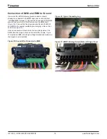
Begin by removing the fuse covers and fuses from the
fuse block (
). Prior to removal, make note of fuse
orientation within the fuse block. Then, position the fuse block
on the backplane of the enclosure and mark the screw holes.
Next, drill pilot holes, through the marks just created, using a
1/8" drill bit.
Finally, attach the fuse block to the backplane using (2) of the
provided #8 sheet metal screws (5/16" head). Fuses can be
reinstalled, but the covers should remain off for subsequent
install of necessary wiring.
Figure 10: Fuse Block with Covers and Fuses Removed
Control Cabinet Penetrations
Only the antenna cable(s) must be routed to the outside of
the control enclosure; all other terminations remain within
the control enclosure. This is done using a specific available
knockout. The location of the correct knockout will vary
depending on the unit model and size of the control enclosure
(see
AGZ and AWV models). On AWS models, field verify an
provide the typical
layout of AWS small and large enclosures). WMC chillers
have available knockouts located on each side of the unit
control enclosure and power box. For AMZ chillers, field verify
available knockout on rear of panel.
First, determine the correct knockout to remove, then remove
it using a hammer, flat screwdriver and pliers. Use the hammer
to gently tap the flat blade of a screwdriver into the open slit
of the knockout. Once enough separation is gained between
the knockout and the panel, use the pliers to fully remove the
knockout. Insert the provided 0.875" grommet into the control
enclosure from the outside. The knockout is now prepared for
routing of the antenna cable(s).
Figure 11: AGZ Small Enclosure Knockout Location
(Rear of Enclosure)
Figure 12: AGZ Medium Enclosure Knockout Location
(Rear of Enclosure)
Содержание AGZ-D
Страница 45: ......


